FM-PP25 PushPier™ System

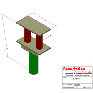
The FM-PP25 PushPier™ System is a hydraulically driven steel underpinning solution engineered for stabilizing and re-leveling existing structures. Unlike driven or helical piles, FM-PP25 segments are pressed to refusal using a hydraulic ram that reacts against the structure’s weight. When installation pressure is sufficient to initiate lift, the pier has achieved the required working capacity. Constructed from 3½″ Schedule 40 ASTM A53 Grade B steel tube with a 12″ × 6″ × ½″ A36 top plate, FM-PP25 is ideal for foundation remediation, slab lifting, and retrofit support in constrained access sites.
Technical Specifications
| Pier Type | Hydraulically driven resistance (push) pier; refusal-based installation |
| Pipe Material | ASTM A53 Grade B, 3½″ Schedule 40 steel |
| Pipe Diameter (O.D.) | 3.5 in (88.9 mm) |
| Wall Thickness | 0.216 in (5.49 mm) |
| Top Plate | 12″ × 6″ × ½″ A36 steel flat plate |
| Ultimate Compression Capacity | 40 tons |
| Allowable Working Load | 30 tons |
| Section Lengths | 12″ nominal segments (stacked via couplers) |
| Connection Type | Full-penetration welded • Threaded coupler • Coupler joint |
| Corrosion Protection | Bare steel • Epoxy coated • Hot-dip galvanized |
| Embedment Depth | To refusal (varies by site; capacity verified by hydraulic pressure / lift) |
| Warranty | Lifetime, transferable |
Applications
- Foundation underpinning and settlement remediation
- Slab re-leveling and structural lift
- Retrofit support in restricted-access areas
- Load transfer to deeper competent strata
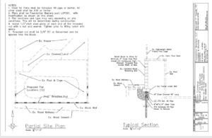
Installation Overview
Pier sections are hydraulically driven using a ram reacting against the structure. Segments advance until installation pressure indicates adequate bearing; once pressure build-up initiates lift, the design working load is achieved. Heads are cut to grade and welded/bolted to the 12″ × 6″ × ½″ A36 plate for integration into footings or grade beams.
Field note: A 3½″ pipe typically requires a field acceptance of ≥30 blows/ft when hammer-driven. For push piers, acceptance is verified by hydraulic pressure and lift (see Proof Test section).
Proof / Load Verification
| Verification Method | Hydraulic pressure × ram area; verify lift initiation and hold criteria |
| Typical Proof Test Schedule | Incremental holds at 0.25DL, 0.50DL, 0.75DL, 1.0DL (10–60 min hold) with displacement checks |
| Documentation | Record gauge pressures, calculated loads, and lift/deflection for each pier |
Engineering Notes
- Allowable working load uses FS ≈ 1.3 on 40‑ton ultimate; soil-controlled capacity is confirmed by hydraulic proof‑load and lift observation (pressure × ram area).
- Because FM‑PP25 is end‑bearing at refusal with no helix plates, capacity is verified by measured load rather than empirical torque correlation. See AC358 torque method for helical piles (AC358 Eq‑8).
- Helical pile published upper‑bound shaft capacities (e.g., 3½″ shafts reported up to ~98,000 lb ultimate) are contingent on meeting torque criteria, helix configuration, and foundation/bracket limits per ICC‑ES reports and manufacturer tables (ICC‑ES ESR‑1854; Ram Jack Product Table). In practice, bracket capacity and footing concrete often govern before reaching those theoretical limits.
- Retrofit helical systems typically rely on a bracket anchored to the footing. Achieving bracket contact may require removing footing overhang to reach reinforcing steel for anchorage; this introduces demolition and potential concrete damage risk. FM‑PP25 uses a compact head plate (12×6×½ A36) with direct load transfer after proof‑lifting.
- Helical compression capacities increase with larger helix diameters and shaft sizes; reaching very high loads commonly requires multiple large helices (e.g., ≥24″) and large shafts. Manufacturer tech literature and AC358 require verifying torque‑to‑capacity correlations and may still require load testing for acceptance (Torque–capacity background).
- Push pier proof‑testing is performed with the retrofit bracket/plate in place, using incremental holds and displacement checks (proof‑test procedure example).
- Foundation Masters Guarantee: We guarantee lift with FM‑PP25 under our engineered installation and proof‑testing protocol.*
*Lift guarantee administered per contract terms, access conditions, and structural safety requirements.
FM-PP25 PushPier™ vs. Ram Jack Helical Piles
Side-by-side comparison of hydraulically driven resistance piers and ICC-ES recognized helical piles used for foundation repair and retrofit.
| Specification | FM-PP25 PushPier™ | Ram Jack Helical Piles |
|---|---|---|
| Ultimate / Allowable Capacity | 40 tons ultimate; 30 tons allowable (working) | Manufacturer literature cites upper‑bound values up to ~98,000 lb ultimate for some 3½″ shafts; actual usable capacity often governed by torque achieved, helix size/number, and bracket/footing limits (ESR‑1854). |
| Corrosion Protection | Bare • Epoxy • Hot-dip galvanized | Polymer coating (e.g., PPA 571ES) or galvanization per ESR/AC228 |
| Noise / Vibration | Low noise; minimal vibration | Low noise; minimal vibration |
| Code / Evaluation | Proof-tested per pier; engineering submittals as required | ICC-ES ESR-1854 (AC358) helical systems; documented torque/length criteria |
| Best Use Cases | Underpinning where structure provides reaction and access is limited | Compression/tension applications; new or retrofit where torque verification preferred |
| Foundation Interface | FM-PP25 PushPier™ | Ram Jack Helical Piles |
|---|---|---|
| Footing Prep / Bracket | Compact plate (12×6×½ A36); direct bearing under center of footer, controlled proof‑lift. | Bracket bears on footing; may require chipping footing overhang to access steel and set anchors; demolition and patching common. |
Performance Takeaway: FM-PP25 delivers measured working capacity at refusal via hydraulic proof-loading, while Ram Jack helicals correlate capacity to installation torque and embedment. Selection depends on access, soils, and whether compression-only or tension loads are anticipated.