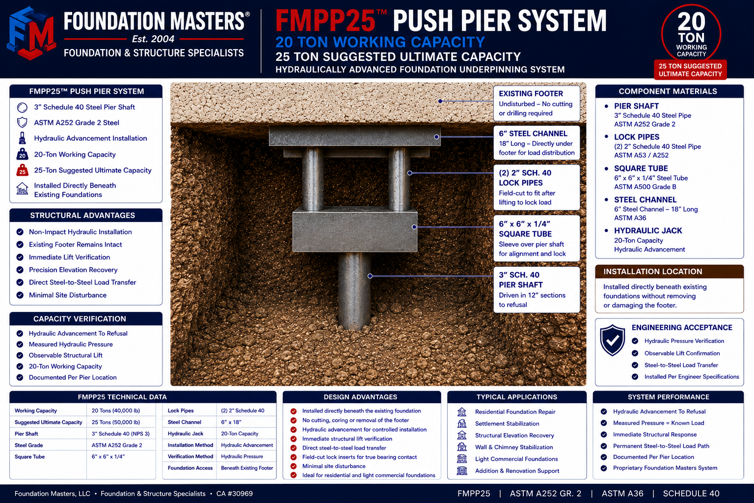
FMPP25 Push Pier System
Hydraulically advanced deep foundation underpinning system engineered for controlled axial load transfer, stabilization, and precision elevation. Capacity is confirmed in real time by measurable structural lift and correlated hydraulic pressure, with documented installation pressures per pier location.
Engineering verification basis: axial stress (σ = P/A) and conservative Euler buckling review (Pcr ≈ 69 tons @ L = 60″, K = 1.0). Mechanical lock inserts are field-cut for true steel-to-steel bearing; shimming is not used as a primary load path.
Florida’s Longest-Running Foundation Repair & Structural Engineering Firm
For more than 25 years, Foundation Masters has designed, engineered, and installed foundation repair, underpinning, deep foundation, waterproofing, and structural stabilization systems. As Florida’s longest-running foundation repair company under continuous ownership, Foundation Masters continues to provide engineered solutions backed by decades of field experience, documented project performance, and proprietary foundation systems developed specifically for Florida conditions.
Engineer Design Reference
Select a pile system to review specifications, installation criteria, and engineered acceptance guidance. Use this index to compare options and keep design decisions consistent across projects.
Verification-Based Acceptance — Documented in the Field
FM-PP25 acceptance is based on measured hydraulic load and observed lift at refusal, with documented pressures per pier location. This produces a defensible underpinning outcome under real site conditions, without relying on torque correlation.
*Administered per contract terms, access conditions, safety constraints, and project-specific engineering evaluation. Refer to the PDF data sheet for procedure and acceptance criteria.
Engineering Research & Technical Publications
The Foundation Masters Research Center serves as our technical engineering library covering deep foundation systems, load testing, structural movement, Florida geology, high-rise investigations, pile design, and long-term building performance.
Engineers, contractors, architects, property owners, and building associations can explore detailed case studies, technical articles, and field investigations that explain the engineering principles behind systems such as the FM-PP25 Push Pier, FM-PP30 Pipe Pile, and other Foundation Masters foundation technologies.
System Overview
FM-PP25 is advanced to refusal by hydraulic press force reacting against the structure. When sustained installation pressure produces measurable structural lift, the pier has achieved the required working capacity. This creates a measured, defensible underpinning outcome under real site conditions.
Refusal + Proof Lift
Segments are pressed until soil resistance produces the required pressure. Proof is confirmed by lift initiation and hold criteria using calculated load with displacement checks.
Designed for Retrofit & Tight Access
Compact footprint and stackable segments make FM-PP25 ideal where access, overhead clearance, or disturbance must be minimized.
Construction
FM-PP25 uses 3″ Schedule 40 steel pipe (NPS 3) with ASTM A252 Grade 2 material (Fy = 35 ksi). Capacity is established in the field by measured hydraulic load and lift confirmation at refusal. A mechanical locking assembly is installed for true bearing engagement—no shimming permitted as a primary load path.
Engineering Verification
Working load is verified by hydraulic pressure and observed lift at refusal. Steel stress check is performed using the pipe steel area.
- Steel Area: 2.24 in²
- Working Stress: 40,000 / 2.24 = 17.9 ksi
- Suggested Ultimate Stress: 50,000 / 2.24 = 22.3 ksi
- Buckling: Euler critical ≈ 69 tons
Mechanical Locking / Preload
After refusal and proof-lift, the system is locked in bearing using a mechanical assembly and preload jack procedure.
- 6″×6″×1/4″ tube + 6″ channel
- 20-ton preload jack procedure
- (2) 2″ Sch 40 inserts
- No shimming as primary load path
For complete procedure, acceptance criteria, and verification details, download the engineer PDF at the top of this page.
Technical Specifications
Note: Final load rating and lift feasibility depend on structure condition, access, and project-specific engineering evaluation.
Components & Field Documentation
Engineer-Sealed Installation Detail
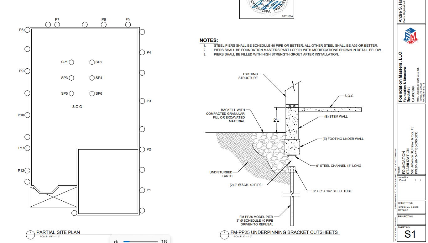
Engineer-sealed installation detail illustrating the FM-PP25 exterior underpinning bracket assembly and FM-PP30 interior slab pier stabilization configuration. Click the drawing to review the complete engineering plan set.
Proven Field Performance
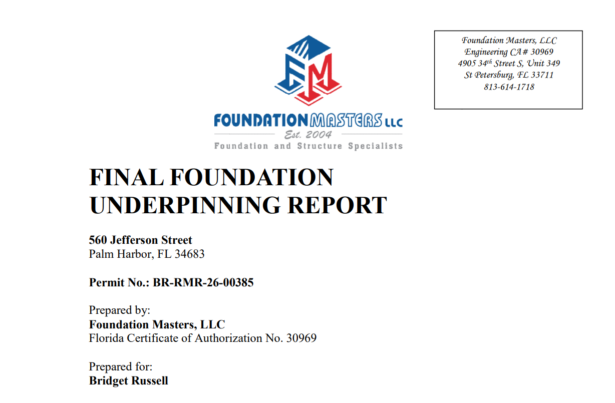
Actual Foundation Masters underpinning project documenting pier locations, installation depths, hydraulic installation pressures, lift verification, and final engineering acceptance. Click the report preview to review the complete project report and installation data.
All images below display full-frame for clean technical presentation.


FM-PP25 Push Pier vs. Helical Retrofit Systems
Values shown are representative and may vary by site conditions. Always consult project-specific engineering.