
Preliminary, and issued for your notes
This is a preliminary design study for 190 SE 2nd Avenue. Nothing on it is final and nothing on it is precious. It exists so the whole team can look at the same building at the same time, mark it up, and send comments back.
Every number here is shown with the method behind it, on purpose. If a figure looks wrong, the working is on the page so it can be checked and corrected rather than argued about. Please read it, make notes, and reply with anything you would change, question, or add.
As replies come in, this page gets updated at this same address. There is no version two to hunt for and no stale copy in circulation. A link sent today still opens the current set next month.
This one needs everybody. Architecture, unit layouts, sales, regulatory, finishes, construction: every discipline on this team sees something the others do not, and the cheapest place to catch it is right here, before drawings start. Corrections are the point of the exercise, not an interruption to it.
Randall Stofft Architects joined the project on 6 September, and Dan Shareef's first review is already in this page. He found five things in the below-grade plan that would not have survived a city review, and every one of them is now drawn. That is the fastest turnaround this document has had, and it is the whole reason it exists in this form.
The structural work is under review by Andre Hawks, PE, our engineer of record. It is our layout rather than his engineering, issued to him as a starting point. His notes come back and the page is updated at this address.
The seven-style elevation study has been taken off. The direction is settled on Masonry Modern and the study had done its work. It is kept on file and can go back up in a moment if anyone wants to revisit it.
190 SE 2nd Avenue, Delray Beach. A preliminary design study for a four-story mixed-use building: retail and showroom at the street, thirteen residential units above, one level of parking below grade, and a pool on the roof. Foundation Masters carries the engineering, the foundation and everything below grade. The architecture is the architect's. What this study does is put the site, the code and the structure on the table early, so the questions that normally surface during construction get asked while there is still time to answer them cheaply.
Everything here is conceptual and issued for review. No dimension is final. The purpose is to put the open questions in one place, each with a number attached, so they can be answered rather than discovered.
The lot at 190 SE 2nd Avenue Delray Beach, and what fits on it
The site at 190 SE 2nd Avenue Delray Beach is 19,675 square feet, with the boundary closing to a hundredth of a foot against the Avirom & Associates survey. It fronts SE 2nd Avenue on the east, SE 2nd Street on the south, a sixteen-foot alley on the west, and an interior lot line on the north.
Ten feet off both street frontages, ten feet off the alley at the rear, and zero on the north interior lot line, confirmed on 4 September. Abutting the neighboring building we may build to the wall. We had been carrying five feet there, and getting it back is worth about 2,250 square feet across the building.
The alley stays at ten. A seven and a half foot reduction had been mentioned but reads as a residential provision rather than a commercial one, so we are drawing the conservative number. Commercial does allow a one foot administrative reduction around the perimeter without going to a board, which is available if it is ever needed.
Two corners carry sight visibility triangles. Twenty feet where SE 2nd Avenue meets SE 2nd Street, ten feet where SE 2nd Street meets the alley, measured from the ultimate right-of-way line for streets and alleys, and from the edge of pavement for driveways. Run against the survey, they cost no floor area at all. At the twenty-foot corner the hypotenuse runs from twenty feet out on one line to twenty feet out on the other, and the building corner sits ten feet back on each. Ten plus ten is twenty, so the corner lands exactly on the line rather than inside it. The alley triangle is smaller than the setback and is clear with room to spare.
What the triangles govern is anything that projects toward those corners, which means the arcade. The two areas are 198 and 50 square feet of ground plane that has to stay open, and the larger sits at the most prominent corner on the site. That is a design instruction rather than a loss, and arguably a gift: an arcade that opens the corner reads better than one that turns it blind.
What the floors actually come to
Areas below are taken off the survey polygon at each level's own setback, so they follow the real shape of the lot rather than a rectangle.
| Level | Elevation | Slab to slab | Floor plate | Envelope |
|---|---|---|---|---|
| Above the roof | +54 to +64 | Pool standing on the slab, deck about +60. Open terrace, bathrooms, lift overrun, plant. Unconditioned only | ||
| Roof slab | +54 | The ceiling limit and the roof are the same line | ||
| Level 4 | +41 to +54 | 13 ft | 14,630 SF | Twenty feet off SE 2nd Street, ten off SE 2nd Avenue and the alley, zero north |
| Level 4 balcony | +41 | 995 SF | Standing on the Level 3 roof along SE 2nd Street. The 2nd Avenue balconies cantilever | |
| Level 3 | +28 to +41 | 13 ft | 15,625 SF | Ten feet off the alley and both streets, zero north |
| Level 3 balcony | +28 | 4,050 SF | Standing on the Level 2 roof, both streets and the alley | |
| Level 2 | +15 to +28 | 13 ft | 19,675 SF 18,145 if the alley holds ten |
To the property line on all four sides. The building wall stays at ten feet and the last ten feet is extension. Office and showroom. The alley side is queried below |
| Level 1 | 0 to +15 | 15 ft | 15,625 SF | Retail and showroom behind the arcade. Finished floor at +3 |
| Grade | 0.0 | 19,675 SF | Lot area per survey | |
| Garage | −9 to grade | 18,301 SF usable | To every property line, inside the permanent sheeting |
That stacks to 65,555 square feet gross across four stories, plus about 5,000 square feet of balcony and terrace standing on the roofs below.
The Owner has queried the Level 2 figure, and the query is a fair one. The mechanism that carries Level 2 out to the property line is the arcade, and there is no arcade on the alley. So how does Level 2 reach the line there?
Because the call answered the alley specifically. Walking the alley side, Tyler Knight put it this way: the ground floor is ten feet off, then "the second floor, the main portion of the building is still 10 feet off, but then you can carry AC or non-AC square footage up to the property line", and the third floor goes back to ten. On that reading it is a second floor allowance rather than an arcade allowance, and the arcade is simply what makes the same ground useful at street level.
It is worth confirming rather than relying on, because it is the single largest number on this page that rests on one sentence. The alley frontage is 153 feet, so ten feet of it is 1,530 square feet. If Level 2 has to hold ten feet back on the alley, Level 2 becomes 18,145 and the building becomes 64,025 rather than 65,555. It is on the zoning verification letter.
The figure has moved three times and every move has been a correction rather than a change of mind. 65,020 at the outset, down to 61,355 when the upper story stepback was first read as applying on three sides, down again to 59,105 when the north setback was carried at five feet. It is back to 65,555 now that the code has actually been read: zero on the north, the stepback on the front alone, and the second floor carried out to the property line. Each of those was cheaper to find now than after drawings started.
Why SE 2nd Street is drawn as the front
We choose which frontage is the front. The only condition is that it faces a main street. Whichever we name carries the twenty foot stepback above the third story, and the other stays at ten.
SE 2nd Avenue is the longer street frontage at about 154 feet. SE 2nd Street is about 117. The stepback is therefore cheaper on 2nd Street, and everything on this page is drawn that way: Level 4 steps twenty feet off SE 2nd Street and holds ten feet on SE 2nd Avenue.
It is worth about 450 square feet of conditioned Level 4 against the alternative. The same 450 moves back the other way as balcony, because area given up at Level 4 becomes terrace on the Level 3 roof, so it is an even trade in area and an uneven one in value. Conditioned space is worth more per foot than outdoor space, even on a top floor.
This is a preference, not a constraint, and it is a simple swap. If there is an address, entrance or design review reason to prefer SE 2nd Avenue as the front, that is a fair argument and the change costs nothing but a redraw. It moves about 450 square feet from interior to balcony and it moves the Level 4 balcony band from 2nd Street to 2nd Avenue, where it becomes larger. Nothing structural changes and nothing below grade changes. Say the word and it flips.
The envelope, as the code actually reads
Settled on 4 September 2026 with the code text open on the call. Everything in this section is what the Land Development Regulations say rather than what anyone remembers them saying, and several of the numbers we had been carrying were wrong in our favour.
Setbacks
| Line | Requirement | What it means here |
|---|---|---|
| Front | 10 ft minimum, 15 ft maximum | There is a ceiling as well as a floor. We had only been carrying the minimum. |
| Side | 0 ft minimum, 5 ft maximum | But a side facing a street or an alley defaults to the rear setback of ten feet. |
| Rear | 10 ft | The alley on the west. |
| North interior line | Zero | Abutting a building, we may build to the wall. This is the 2,250 square feet we have been chasing since Bart raised it, and it is confirmed. |
| Above the third story, front | 20 ft | Applies to the front only. |
| Above the third story, sides and rear | Not addressed | The code sets a front stepback above the third story, and a thirty foot side or rear stepback only where a residential district is abutted, which we do not. It says nothing about sides and rear otherwise, so they stay at ten feet on the fourth floor. That is roughly 2,500 square feet we had given away. |
| Perimeter reduction | 1 ft | Available administratively on the commercial component without going to a board. A ten foot setback can be nine. |
Which street is the front is our choice. The rule is only that it faces a main street. Whichever frontage we name as the front is the one that carries the twenty foot stepback above the third story, and the other stays at ten. That single decision is worth more than any dimension on this page, and it should be made deliberately rather than inherited from the address.
The arcade, which is how the street level gets its area back
The ten foot setbacks take real area off a small lot. The arcade is the instrument that gives it back, and it has been approved in this city before on that basis.
| Dimension | |
|---|---|
| Arcade height | 10 ft minimum, 20 ft maximum |
| Column position | On the property line, landing on the perimeter wall. A separate note in the record puts the column face two to five feet off the face of curb, which would sit outside the line. The two readings conflict, and it is open item 4 |
| Column width and depth | 1 ft |
| SE 2nd Avenue | The arcade may run to the property line |
| SE 2nd Street | It may run past the property line, because the sidewalk sits beyond it and there is a landscape swale rather than parking to displace |
| The alley, west | No arcade. The second floor cantilevers over the ten foot setback to the property line, and that setback carries parking underneath it |
| The north line | Nothing to project over. The wall stands on the property line from the ground up |
The second floor may extend all the way out to the edge of the arcade, and it may do so as conditioned space. Not a balcony, not a terrace, air conditioned square footage carried out over the arcade to the property line and, on the 2nd Street side, beyond it. That is the second floor only. The third and fourth may not follow it out.
The third floor gets the consolation prize, and it is a good one. The floor cannot go over the arcade but the balconies can, so the third story along both street frontages gets a continuous balcony band standing on the arcade roof rather than cantilevered off the face of the building. That is the cheapest balcony on the project, because the structure is already there to carry the arcade.
The second floor gains on three sides, and by two different mechanisms
This is worth being precise about, because the two are not the same thing and one of them is much easier than the other.
On the two street frontages it is the arcade. The arcade occupies the ten foot setback, its columns stand on the property line, and the second floor rides out over the top of it as conditioned space, reaching the line. On SE 2nd Street it may be able to pass the line, because what sits beyond it there is a landscape swale rather than a walk hard against the boundary. That is upside rather than budget, and it is the only version that would need a foundation on city ground.
On the alley it is a plain cantilever, and it is the simplest of the three. The building stands ten feet off the alley at ground level, that ten feet carries a row of parking, and the second floor projects out over it to the property line. No columns in anybody's right of way, no encroachment agreement, no commission. We are projecting over our own land and covering our own parking while we do it.
On the north there is nothing to gain, because there is nothing given away. Abutting the neighboring building, the wall stands on the property line from the ground up. It is already where the second floor would project to.
So the second floor is the largest plate in the building by a wide margin, and it is the only floor that gets this. Everything above it returns to the ten foot line. Which is exactly the point, because what the second floor is really building is the third floor's balconies.
The balconies, and why the good ones are almost free
The third floor steps back to the ten foot line. The second floor does not. So the entire roof of the second floor, the whole band that projects out over the arcade and over the alley parking, becomes usable outdoor space for the floor above it, standing on structure that is already being built.
No cantilever. No exposed steel reaching out into salt air. The slab is being poured and strengthened to carry the arcade regardless, so the balcony above it costs a railing and a waterproofing detail rather than a structural system.
The move is to run one continuous railing around the whole projection and divide it between the units with railings rather than break it into separate boxes. It reads as one long terrace across both street frontages, every third floor unit opens onto it, and it is cheaper to build than the fragmented version. On the ten foot setback alone that is roughly 2,250 square feet across 85 feet of SE 2nd Street and 140 feet of SE 2nd Avenue, before counting the deeper part of the band that sits over the arcade itself.
The fourth floor works the same way on the front and differently everywhere else. Because Level 4 steps back twenty feet from SE 2nd Street while Level 3 sits at ten, a ten foot band of Level 3 roof runs the length of that frontage, and the fourth floor balconies stand on it. Roughly 1,000 square feet, again on structure that already exists.
On SE 2nd Avenue, the alley and the north line, Level 4 sits flush above Level 3 with nothing beneath it to stand on, so those balconies cantilever. Balconies may encroach into the setback provided they are not enclosed, so they are permitted, they simply have to be hung off the slab. That is straightforward to build and it is the right place to spend the money, because those are the units with the long views.
Two things about cantilevered balconies that belong in the specification rather than in a later conversation. Keep them modest and shaped. A very large square balcony is expensive, and every square foot of it is a square foot of sellable area given away in a market where the beach four blocks east is already the amenity. A recessed or partly covered balcony costs less and lasts longer than a fully exposed one.
And a cantilevered slab puts its tension steel at the top face of the concrete at the outermost edge, in continuous salt air. That is the exact condition that produces spalling in coastal Florida buildings at twenty to thirty years. Protective coatings on the reinforcement are cheap at the mill and impossible afterwards, and a specified corrosion protection system on every exposed balcony is something this building can put in its listings that almost nothing else in the state can.
The footprint of each floor
The stack
| Level | Elevation | Use and envelope |
|---|---|---|
| Garage | −9.0 to grade | To the property line on all four sides |
| Level 1 | 0 to +15 | Retail, showroom and lobby behind the arcade. Finished floor at plus three. Fifteen feet slab to slab against a code minimum of twelve for commercial |
| Level 2 | +15 to +28 | Office and showroom. The building wall stays on the ten foot line and conditioned space extends from it out over the arcade to the property line. Thirteen feet slab to slab |
| Level 3 | +28 to +41 | Eight units, back to the ten foot line, balconies over the arcade. Thirteen feet slab to slab |
| Level 4 | +41 to +54 | Five units. Twenty feet back on the front, ten on the sides and rear |
| Roof slab | +54 | The ceiling limit and the roof are the same line. The four floors take the whole fifty-four feet |
| Above the slab | +54 to +64 | Unconditioned only. Pool and deck, open terrace, bathrooms, lift overrun, railings, screened plant |
Thirteen units, eight on Level 3 and five on Level 4, at about 1,300 to 1,600 square feet each. Level 2 is now office and showroom in full rather than a shared floor.
The nine feet nobody had claimed
Fifty-four feet is not the top of the building. It is the top of any ceiling in it, and the slab is permitted to run all the way up to it. We had been drawing a roof at plus forty-five with the amenity squeezed into the nine feet above, which spent that height on a gym instead of on the apartments.
Put the four floors into the full fifty-four instead and the residential floors go from ten feet slab to slab to thirteen. That is about eleven feet clear once structure and a drop ceiling are taken out, against the ten feet clear that actually sells at this price. Nine feet of height, distributed where buyers stand in it.
What that costs, and it is worth knowing precisely. The zone above fifty-four takes architectural appurtenances only: lift overruns, bathrooms, railings and screened plant, which are all explicitly permitted, plus the pool and an open terrace, which are not conditioned space. What cannot go up there is anything enclosed and air conditioned. An enclosed gym does not qualify. Neither does a business centre. An open air fitness terrace does.
So the enclosed amenity comes back inside the building rather than sitting on the roof, and that is the trade: nine feet of ceiling across four floors against an enclosed gym on the roof. It is not a close call.
The pool sits on top of the fourth floor rather than down inside it. The roof slab is at fifty-four, the vessel stands on that slab, and the deck lands around plus sixty, well inside the ten foot appurtenance zone. Nothing about the pool enters the occupied building at all.
That is the clean answer and it removes a problem rather than managing one. No local well dropped into the top of Level 4, no vessel hanging over anybody's ceiling, no argument about whether the unit beneath it costs more to insure. It also means the fourth floor plan is not shaped around where the pool happens to be, which is a real freedom for the architect.
Either way the walls of the vessel are thickened, freestanding, and set directly over the pile caps and columns, so the pool walls are themselves the load bearing members and the suspended slab beneath carries only the water. That detail is what makes the pool a foundation problem rather than a floor plan problem, which is the right place for it to be.
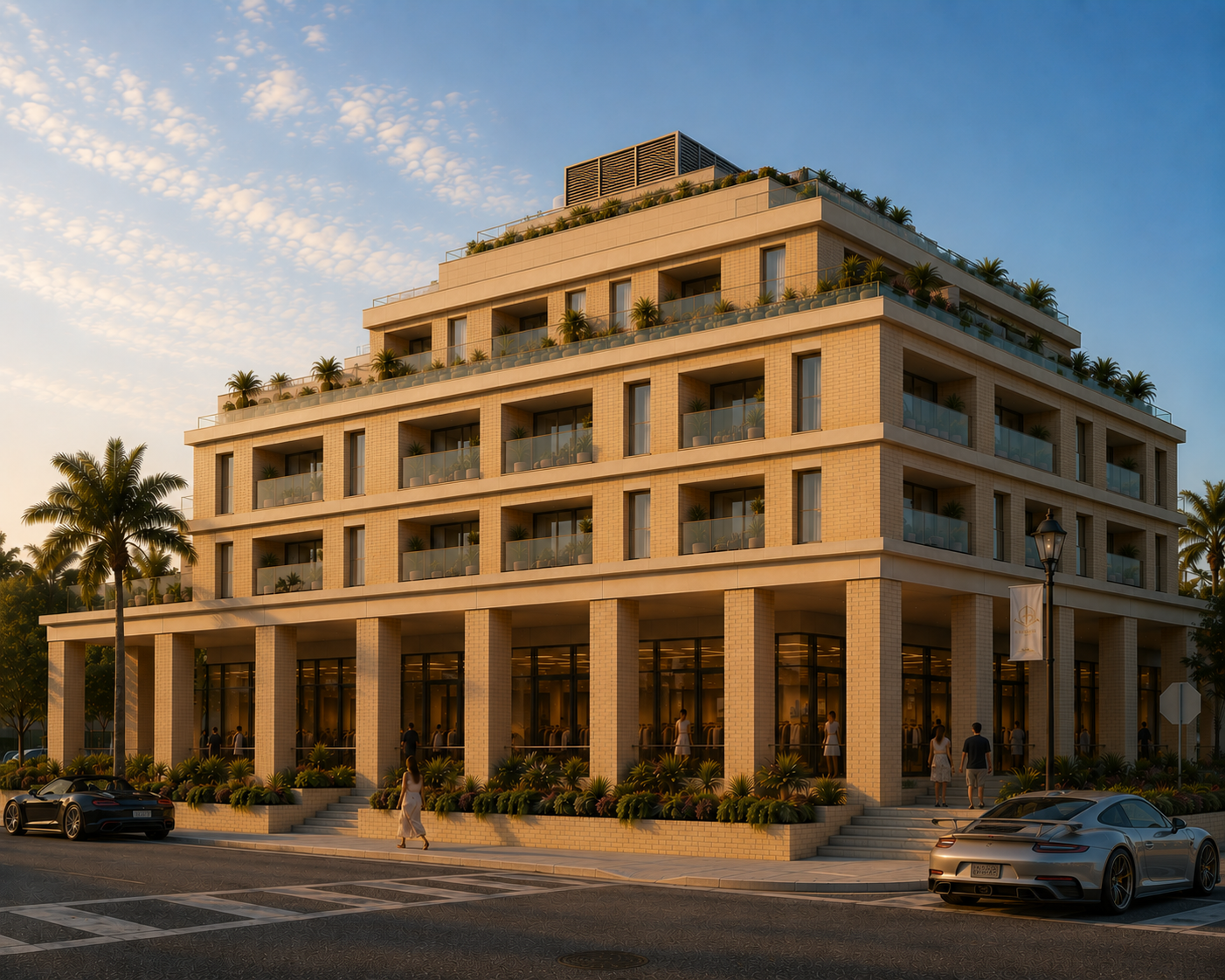
Three things in the building worth looking at
The image at the top of this page shows the character. Three things in it are worth looking at directly, because each one is a decision rather than a drawing choice.
The arcade reads as depth rather than as a line, which is what a covered walk actually does to a street frontage. It puts the showroom glass in shade, it carries the second floor out to the property line above it, and its roof becomes the third floor's terrace. It is the cheapest square footage on the project by a wide margin, because one slab does three jobs.
The setbacks above it are the code working in the owner's favour. Each step buys private outdoor space that costs no floor area at all: about 4,050 square feet on the Level 2 roof for the third floor, and 995 more on the Level 3 roof for the fourth. Around 5,000 square feet of terrace standing on structure that is being built anyway.
And the building uses its full height. Fifty-four feet is the top of any ceiling rather than the top of the building, so the four floors take all of it and the residential floors run thirteen feet slab to slab instead of ten. That is about eleven feet clear where people live. The pool, the bathrooms, the lift overrun and the plant sit in the ten foot zone above, none of it conditioned, none of it competing with the apartments for height.
On the style. Masonry Modern: wide bays, recessed balconies rather than cantilevered, a continuous band at every floor line, deep reveals, and a flat top finished with a slim projecting cornice. The recessed balcony is the choice that matters beyond appearance, because it keeps the slab inside the envelope and takes the most corrosion exposed reinforcement in the building off the outside face.
The image is an impression, not a measurement. It shows proportion, depth, and how the building meets the sidewalk. Material, color, the window pattern and the character of the ground floor belong to the architect. The drawings further down this page are the dimensioned record, and where the two disagree the drawings are right.
The first floor sits three feet above grade, and that is deliberate
The first floor is set three feet above existing grade. That lift does two things at once. It clears the requirement that the finished floor sit eighteen inches above the crown of the street, and it keeps the parking level below the point at which the town would count it as a story, which happens at roughly two and a half feet of exposure.
It also buys the garage room. Floor at minus nine, first floor at plus three, gives twelve feet gross for the slab, its framing, hung sprinkler, duct, conduit and lighting, and the clear height a car needs underneath. That is comfortable rather than tight.
Three feet is easy in section and hard at the sidewalk
That lift has a consequence none of the massing drawings show. Because the garage runs out to the property line, the first floor sits on the garage roof, and the finished floor is therefore three feet above the public sidewalk along 288 feet of street frontage. Nothing on the ground floor meets the sidewalk at the sidewalk’s level.
Three feet is four steps. On a retail frontage that is the difference between a shop somebody walks into and a shop somebody looks at, so it is worth solving properly rather than absorbing.
The instrument is slope, not steps. A ramp at one in twelve climbs three feet in thirty-six feet, but it needs handrails both sides and a landing part way up, and it looks like a ramp. A walk at one in twenty needs sixty feet and needs neither, because at five per cent it is not a ramp at all, it is a graded walk. Sixty feet against 288 feet of frontage is a fifth of one side. That is the version that reads as landscape rather than as accessibility equipment.
And the corner is where it wants to happen. The twenty by twenty sight visibility triangle already keeps the SE 2nd Avenue and SE 2nd Street corner clear of building, so it is the one part of the frontage with room to spare, and it is where anyone walking up from Atlantic arrives. A corner that rises gently from the crosswalk into the arcade is a front door. The same three feet delivered as a ramp beside a blank wall is not.
The cheapest move, though, is to make the three feet smaller. Twelve feet from minus nine to plus three was sized for comfort rather than driven by anything. Cars need about seven feet of clear height, eight feet two on the accessible route, and the mechanical lift bays are getting a local pit in any case. Raising the garage slab a foot and dropping the first floor six inches would put the step at two feet six, shorten the graded walk from sixty feet to fifty, take a foot of excavation and sheet pile out of the whole perimeter, and keep the slab further above the water table. Three good outcomes from one decision. What stops it going lower is the rule that the finished floor sit eighteen inches above the crown of the street, and whatever base flood elevation applies to this parcel, and neither of those has been checked.
And the climb cannot happen across the arcade. Ten feet of arcade, less a three foot two inch pier standing on the property line, leaves six feet eight inches. Six risers need six feet of that and then a landing, so a flight of steps running from the sidewalk toward the shopfront would consume the arcade and still not work. The climb has to run along the frontage instead.
Two consequences fall out of that plan. The first is that a stretch of frontage becomes circulation rather than shopfront, so the ramp wants siting where the frontage is lobby or service rather than where it is retail. The second is that every inch off the floor level is twenty inches off the ramp, which is why the finished floor elevation is worth settling before anyone designs the ground floor. The flood half of that question is now answered: the survey puts the parcel in Flood Zone X, so there is no published base flood elevation pushing the floor up, and the governing number is the crown of the street alone.
One interaction to check at the corner. Sight visibility is measured through a clear band above grade, understood to run from two and a half to eight feet. A raised deck at plus three sits inside it, and so does planting standing on the seat wall. The corner is where the graded approach wants to be and it is also the one place where a raised surface may not be permitted. It needs confirming before the corner entrance is drawn.
This also decides where the arcade columns go, and the notes give two answers. The arcade is the ten foot setback, which puts the columns on our own property line, standing on the perimeter wall. A separate note has the column face two to five feet off the face of curb, which with the right of way in between would put them well outside the line. Everything on this page is drawn the first way, because it is the reading that matches what the arcade is for and it needs no foundation on city ground.
The difference is not academic at the street. A public sidewalk cannot be raised three feet, so if the columns move out there the covered walk stays at grade and the step lands at the shopfront rather than at the property line, with the colonnade in front of it. That is a different building at the pavement. The column position and the floor level are one decision, not two, and they are open items 4 and 5.
The rooftop pool
A 25 by 15 pool standing on the roof slab at plus fifty-four, five feet deep with three foot shallow ends, its deck around plus sixty. Thirteen units do not need a large pool; they need a good one, with room beside it for loungers and an open covered area.
Fifty-four feet is the top of any ceiling, and the slab may run right up to it. Above that sits a ten foot zone for architectural appurtenances: lift overruns, bathrooms, railings and screened plant, all explicitly permitted. Nothing conditioned may go above fifty-four. An enclosed gym does not qualify. An open air one does. The pool does, because it is not conditioned space.
So the four floors take the whole fifty-four feet and the roof slab is the ceiling limit. The enclosed amenity comes inside the building; the pool, an open terrace, the bathrooms and the plant sit above. That buys about eleven feet clear on the residential floors, and none of it needs a discretionary approval from anybody.
Raising the pool instead of dropping the vessel
The pool deck is raised above the roof slab and you step or ramp down from it to the amenities. That arrangement, which the Maxwell used four blocks from here, solves two problems at once.
The vessel sits above the roof slab, not through it. At five feet of water the vessel runs a little over six feet from the waterline to the underside of the shell. Standing on a roof slab at fifty-four, that puts the deck around plus sixty and the whole of it inside the appurtenance zone. The floor below keeps its full ceiling and the soffit over the deep end that has been on the open items list since the start simply goes away.
And the pool stops sitting over anybody's home. A pool above a private residence is expensive to build and worse to insure. The pool goes over the stairs, the shafts, the bathrooms and the structure instead. The walls of the vessel are thickened, freestanding and set directly over the pile caps and columns, so the pool walls are themselves the load bearing members and the suspended slab beneath carries only the water.
There is a dividend in this that is easy to miss, and it is the reason the whole arrangement is worth the trouble. Because nothing residential sits under the pool, the fourth floor no longer has to be pushed down to clear a vessel above it, and the height that frees goes back into every floor in the building. Ten feet clear, drop ceiling to floor rather than slab to slab, is what sells at this price, and this is how we get there.
It holds just under ten thousand gallons. Water alone is 41.7 tons; a ten-inch reinforced shell is another 41.2. Together they put roughly 442 pounds per square foot on whatever is underneath, about three times what the floor around it is designed to carry. Eighty-three tons over 375 square feet is a heavy bay, not an impossible one.
The vessel needs six feet four inches below the water line at five feet of water, and five feet four at a uniform four feet. That one foot is the whole argument, because it converts directly into clear height beneath the deep end. Up to twenty-five per cent of the roof may be covered by a structure reaching sixty feet, which is where the shade element and the bathrooms go.
Two scopes follow from putting water above dwelling units. The waterproofing becomes a containment assembly rather than a membrane: a waterproofed tray under the shell, drained to a visible point, with leak detection between shell and tray so a failure announces itself before it appears on a ceiling. And the shell is the most aggressive corrosion environment in the building, with chlorinated water on one face, salt air on the other and wet and dry cycling at the water line. That makes it the clearest case on the project for stainless reinforcement to ASTM A955 in the shell, coping and deck penetrations.
One siting note carries into the structural layout. Eighty-three tons at the top of the building travels down every column beneath it and into the piles. Landing the pool over the stair and elevator core, or over a column group at the north end where the building is flush to the lot line, adds load to columns that already exist. Landing it mid-span means a transfer at the roof, which is structure carried through four floors for one amenity.
Where the walls above land, and what that costs
The floors do not stack, and the way they step is easy to get wrong. Working up from the street: Level 1 is ten feet back. Level 2 is also ten feet back, and then carries conditioned space out over the arcade to the property line. Level 3 is ten feet back. Level 4 is ten on the sides and twenty on the front. Read the outermost edge of each floor and it steps back ten feet a floor from the second up, which is exactly how it was described on the 4 September call.
The distinction that matters structurally is between a building wall and an extension. Level 2 does not have a wall on the property line. Its wall is at ten feet, in line with Level 1 below and Level 3 above, and what reaches the property line is a ten foot deep extension sitting on the arcade. In Tyler Knight's words on the call: "the main portion of the building is still 10 feet off, but then you can carry AC or non-AC square footage up to the property line". Conditioned space at the property line, yes. A load-bearing line there, no.
An earlier version of this drawing showed a Level 2 wall standing on the property line. That put load in the wrong place and made the ten foot line look lighter than it is.
The ten foot line carries the building
Once Level 2's wall is put where it belongs, the ten foot line is not one line among three. It is the building's exterior wall at every level except the fourth floor front, and it runs continuously from the Level 1 slab to the roof.
| What it carries | On the sides | On the front |
|---|---|---|
| Floor slabs inboard, 11 ft 9 tributary | 4 slabs, 9.4 kip/ft | 3 slabs, 7.1 kip/ft |
| Level 2 extension and its roof, 5 ft tributary | 2.0 kip/ft | 2.0 kip/ft |
| Exterior wall itself | 3 stories, 2.6 kip/ft | 2 stories, 1.9 kip/ft |
| Total on the ten foot line | 14.0 kip/ft | 10.9 kip/ft |
Fourteen kips per foot governs, and it is on the sides rather than the front, because Level 4 keeps its wall on the ten foot line there instead of stepping to twenty. That is the opposite of where most people would look for the worst case.
It still lands on the wall, and it still costs no parking
The answer does not change, only the size of it. There is no garage column under the ten foot line and the nearest one is more than twenty feet further in, so a thickened band in the Level 1 slab carries it six and a half feet across to the perimeter wall.
| Take it to ground | Land it on the wall | |
|---|---|---|
| New columns and pile caps in the garage | 17 | none |
| Where they stand | In the first stall of every bank | Nowhere. It is inside the slab |
| Stalls lost | 8 to 10 | none |
Of the fourteen kips per foot, about nine point eight goes into the perimeter wall and four point two runs inboard to the first garage line. The wall is already there, already continuous and already on piles.
This is the one number on the page that is still in two states, and it is worth being plain about which. The perimeter wall's own load is settled at six point seven kips per foot, and the pile schedule is drawn on it: one FM‑PP45 every six feet six, eighty-four piles, twenty-one point eight tons apiece at two to one. That number does not move.
The nine point eight kips per foot off the ten foot line is the part in question. If the band is confirmed, the wall goes to sixteen and a half kips per foot, nine thousand kips over five hundred and forty-five feet, and the perimeter takes a hundred and ninety-eight FM‑PP45 at two feet nine, or ninety-one FM‑PP100 at six feet. Both cases are set out in the perimeter section above, priced separately, so that whichever way the engineer of record calls it there is a schedule already standing behind it rather than a revision.
What sits at the property line, and what sits at twenty feet
At the property line, only the Level 2 extension. Five feet of tributary on two slabs plus its own skin, about two and a half kips per foot, onto the arcade column and straight into the wall below it. Light, and it explains why the arcade column never needed a foundation of its own.
At twenty feet, only Level 4 on the front. One story of wall and the roof edge, a little over two kips per foot, carried by a beam in the slab it stands on. Nothing goes to ground.
The rule this all comes down to. A line that stacks three or more levels earns its way to a foundation. A line that carries one or two gets picked up by a beam in the floor beneath it. The ten foot line qualifies and then some. The property line and the twenty foot line do not.
The arcade is the setback, and that is the whole point of it
Facing a street on three sides, this lot has to hold ten feet back on all three. The arcade is what gets that ten feet back. On the 4 September call the reasoning was put plainly: the ten foot setback is required, then, in Tyler Knight's words, "we can do the arcade to make up for that", and it "allows you to at least get some more sellable square footage into that area that you technically lost due to that setback requirement".
Corrected 6 September, by Dan Shareef at Randall Stofft Architects. Two things in this section were wrong. The arcade clear width is measured from the interior face of the column, not from the property line, so a one foot column standing on the line gives nine feet clear rather than ten. And the city wants the column face between two and five feet off the face of the curb, which puts it in the right of way rather than on our line. That is the reading set out further down as the conflict, and it is now the base case rather than the alternative. Everything below is written on the old reading and stands only until the Pre-App fixes the curb line. The drawing above shows both, the on-line version solid and the off-the-curb version dashed. The dashed one is now the likely answer.
So in the base case the arcade occupies exactly the ten feet between the property line and the shopfront. Its columns stand at the property line, directly over the perimeter wall, and need no foundation of their own. The wall is already there, already on piles, already carrying the building. Picking up a one foot column at the top of it costs a rebar detail.
An earlier version of this page had those columns four feet outside the property line, on city ground, with pile caps of their own. That was a misreading, caught on review. It made a separate foundation system out of a problem that does not exist in the base scheme. The drawing above is the corrected one.
Going past the line is an option, not a requirement
On SE 2nd Street only, the arcade may be able to push past the property line, because what is in front of the building there is a landscape swale rather than a walk hard against the line. The view on the call was that the city would look favorably on a wider covered walk, and that "since it's a landscape swale, I think we can get away with that". Level 2 could then follow the arcade out, though only Level 2: the third and fourth floors cannot be carried past.
Two things follow, and they matter.
It is upside, not budget. Every area figure on this page already stops at the property line. Level 2 is 19,675 square feet because it runs to the line on all four sides. Anything gained past the line on SE 2nd Street would be additional. Nothing on this page depends on getting it.
It is the only version that needs foundations on city land. Push the column out and it no longer lands on the wall, so it needs its own pile cap outside the sheeting, hanging on its own piles rather than bearing on the ground the wall is holding back. Eight columns, one FM‑PP45 apiece. Plus an encroachment instrument, a subsurface utility locate at every cap, and swale storage volume put back somewhere else on site.
This conflict is now resolved against us, and it belongs on the zoning verification letter anyway. Alongside the ten and twenty foot arcade heights, the note was also given that the column face must sit between two and five feet off the face of the curb. With something like twelve feet of right of way between our line and the curb, that would place the column seven to ten feet outside the property line rather than on it. The two readings cannot both describe the base case. This is exactly the kind of thing to have answered in writing by the city rather than settled by recollection, ours or anyone else's, and the request is already drafted.
The rule that makes the answer not matter much
Whatever the city says, Level 2 should cantilever from our own column line rather than bear on the arcade columns. Then the arcade carries the arcade and nothing else.
If the arcade stays inside the line, this costs nothing at all. If it goes outside and the permission is later withdrawn, the worst case is that we lose a colonnade instead of a floor. Same drawing effort either way, and the choice disappears the moment the framing is drawn, which is why it is worth saying now.
On SE 2nd Avenue this is the biggest question mark on the project, and it is not ours to settle. The curb line on that street is unresolved, and until the city fixes it nobody knows where our building envelope stops. That sets the arcade, the arcade sets the column, the column sets whether we are placing pile caps in the right of way, and the envelope sets the garage below it.
So the Pre-App meeting is on the foundation critical path, not only the architect's. Everything else below grade is indifferent to it: the perimeter wall, the structural mat, the pile schedule and the boring program are the same whichever way the right of way resolves. The arcade caps are the single exception, and they are the one thing we cannot draw until the curb is fixed.
The perimeter is a system, not a wall
The outside of this building is not held up the way the inside is. The inside is columns on pile caps. The outside is four things acting as one, and it is the part of the job Foundation Masters does every day.
Twenty foot sheet piles go in first and stay in. They hold the neighbors' ground while we take nine feet out, and once the wall is poured against them they never come out. Eleven of their twenty feet are below the cut.
The vertical load does not go into the sheeting. That is the point most people miss. The sheeting retains; it does not carry the building. Under the wall we pour a spread footer with pipe piles driven under it, a single row of FM‑PP45 at six feet six on centre, running down to competent limestone. That is a four and a half inch pipe in A252 Grade 2, carried at twenty-two and a half tons working on a two to one safety factor, and it is a Foundation Masters system we install and warrant ourselves. Then the wall is cast against the sheeting and welded to it with studs, so the sheeting is the back form and the finished wall, the footer and the sheeting act as one member.
That is the assembly the lifetime warranty sits on, and it is why the perimeter has no isolated pile caps in it. It is continuous, so it verifies as a line rather than hole by hole.
What the perimeter has to carry
Five hundred and forty-five feet of wall, and it is worth separating two loads that have been added together on earlier versions of this page. One of them belongs to the perimeter and always will. The other one is still a question.
The load that is settled
The wall carries itself, the Level 1 slab edge and the arcade floor over it, the arcade column and the Level 2 slab running out to the property line, and the exterior wall above. That is the perimeter's own work, and it does not depend on any decision still open.
| What the wall carries | Per foot of wall |
|---|---|
| Cast in place wall, 12 in, footer to Level 1 | 1.9 kip/ft |
| Level 1 slab edge and arcade floor | 2.0 kip/ft |
| Level 2 over the arcade and out to the line | 2.2 kip/ft |
| Exterior wall and finishes above | 0.6 kip/ft |
| The perimeter's own load | 6.7 kip/ft |
Six point seven kips a foot is not a heavy line, but it is heavier than a small pile carries once the safety factor is honoured. One FM‑PP45 every six feet six carries it, eighty-four piles over the whole perimeter, at forty-three and a half kips or twenty-one point eight tons apiece against a twenty-two and a half ton working capacity. That is the pile working at ninety-seven per cent of what we will warrant it to, which is where a production pile should sit.
The smaller FM‑PP30 was carried until the safety factor was applied and it does not survive it. Its product sheet publishes thirty tons allowable, but at two to one on a forty ton ultimate it is a twenty ton pile, and twenty tons on this line means a pile every six feet with no margin left for a heavy stretch. The next size up costs a slightly larger pipe and buys back the margin. That is the trade, and it is an easy one.
One row, not two. The eccentricity between the wall face and the footer is real, but it is answered by the footer acting as a beam in a wall that is welded to the sheeting along its whole length, not by a second line of piles. A single row at six feet six is also fast, verifiable pile by pile and driven on the same equipment as the rest of the site.
The load that is not settled
The building's own ten foot wall line puts fourteen kips per foot onto the Level 1 slab with no garage column under it. The scheme drawn two sections above carries about nine point eight of that six and a half feet across to the perimeter wall in a thickened band. If that is the instrument the engineer of record confirms, the perimeter is not carrying six point seven. It is carrying sixteen and a half, and the pile schedule changes shape.
| System | Working, at 2:1 | Perimeter alone, 6.7 kip/ft | With the band, 16.5 kip/ft |
|---|---|---|---|
| FM‑PP45 | 22.5 ton | 6 ft 6, 84 piles | 2 ft 9, 198 piles |
| FM‑PP100 | 50 ton | more pile than the line needs | 6 ft, 91 piles |
This is the cleanest illustration on the page of why question four matters. The band is drawn because it costs no parking, and it still looks like the right answer. But at two to one it is the difference between eighty-four FM‑PP45 on the perimeter and a hundred and ninety-eight, or a step up to the FM‑PP100 at six feet and ninety-one. That is a number a supplier prices. The base case is drawn and quoted on the perimeter's own load. The band case is carried alongside it until the engineer of record settles which one is real.
The systems, and where the numbers come from
These are Foundation Masters' own pile systems rather than a generic call-out, which is the reason the capacities can be stated at this stage of a design at all. Each one is installed, torque and pressure logged, and warranted by the same company that specified it.
4½ in outside diameter, 0.237 in wall, ASTM A252 Grade 2. Forty-five ton nameplate, twenty-two and a half tons working at two to one. The perimeter wall, one every six feet six. Eighty-four piles.
8½ in outside diameter, 0.322 in wall, ASTM A252 Grade 2. One hundred ton nameplate, fifty tons working at two to one, a hundred and fifty ton steel section. The interior pile caps, three to eight a cap. A hundred and seventeen piles.
FM‑PP30 · not used
3½ in Schedule 40, ASTM A53 Grade B. Carried on earlier versions of this page and dropped once the safety factor was applied. Twenty tons working left no margin on either line. Recorded here because the decision is worth seeing.
Also on file. The FM‑PP30‑FS is the weak soil variant of the family and the detail behind it is the one to borrow if the borings come back with a soft seam above the limestone, whatever pipe size it ends up on. The full range is at foundationmasters.com/our-products, and the pile driving and pipe pile pages set out the installation method behind these numbers.
The structure, first pass
We now know enough about the envelope to start setting columns, and the column grid is the decision everything below grade waits on. It sets the pile caps, it sets the borings that have to prove them, and it decides how many parking spaces survive.
The conflict is real and worth naming before the drawing. A building wants columns every twenty-five to thirty feet, because that is where floor framing is cheapest. A parking bay is eighteen feet of stall, twenty-four feet of aisle and eighteen feet of stall, so any column inside that sixty feet lands in a drive aisle or in a car. Those two numbers are not close, and the garage is the one that cannot bend. You can move a beam. You cannot move a car through a column.
Sixty feet was the wrong answer, and the reason is headroom rather than cost
The obvious move is to span the whole bay. Columns only at the backs of the stalls, sixty feet apart, nothing in between. It looks clean on a plan.
It does not survive contact with the section. This is not a parking deck carrying another parking deck. It is a transfer level carrying four stories of building, so the members are several times what a normal garage needs. A sixty foot span at that load is a beam somewhere around forty-five inches deep. The garage is twelve feet gross from minus nine to plus three. Take forty-five inches out of it and the clear height under the beam line is a little over eight feet.
Eight feet parks a car and puts the mechanical lifts in doubt. Cars want seven feet and the accessible route wants eight feet two, so a sixty foot bay works for parking as parking. A two-car stacker wants eleven feet six to fourteen overall, and even with a three foot pit under it, eight feet three above the floor leaves nothing in hand.
The lifts are the cheapest spaces on this project and they are what closes the remaining parking gap. Trading them for a tidier plan is trading the answer for the drawing.
Split the bay, and put the columns in a lane of their own
So the columns go into a strip of their own rather than onto a stall stripe. Running north to south there is a line at the back of each stall bank and, since the review on 6 September, a line set fully inside the bank rather than on the aisle edge, so that the drive aisles are twenty-four feet clear between column faces. In the other direction the lines run twenty-six to thirty feet apart, three stalls at nine feet plus the two and a half foot column strip.
That strip is the whole trick. A column parked on a stall stripe steals a foot and a quarter from the car either side of it and ruins both. A column standing in its own lane costs the lane and nothing else, so the penalty is about one stall per bank rather than one stall per column.
Longest span drops from sixty feet to twenty-six and a half. The slab spans the short way, fifteen and a half to twenty-six and a half feet between the east-west lines. The girders span the long way, twenty-six to thirty feet, at a depth nearer twenty-four inches than forty-five. That leaves about ten feet clear under the girder line and more between girders, which is comfortable rather than marginal, and the stackers work with the local pit already in the scheme.
The east line does not run square, because the lot does not
The lot is not a rectangle. It is roughly fourteen feet wider at the north end of SE 2nd Avenue than at the south, and the whole east boundary rakes across that distance. An orthogonal grid leaves a wedge along the Avenue with no support in it, and that wedge is not spare ground: the building above sits on it, and at the second floor it runs all the way out to the property line.
So the east column line rakes with the property line rather than fighting it, holding about twelve feet inside the wall for its whole length. The bay it makes with the next line inland varies from roughly thirty feet at the north to nineteen at the south, which is a shorter span rather than a longer one, so it costs nothing structurally. It also puts the columns under the building's own east face instead of somewhere near it.
| Span the bay | Split the bay | |
|---|---|---|
| Longest span | 60 ft | 26 ft 6 |
| Girder depth, rule of thumb | about 45 in | about 24 in |
| Clear height under the girder | about 8 ft 3 | about 10 ft |
| Accessible route, 8 ft 2 required | Marginal | Clears comfortably |
| Mechanical lifts, on headroom alone | In doubt | Work, with the local pit |
| Interior columns | 12 | 24 |
| Stalls | Set out properly in the parking section below, on the corrected layout. It is 27 | |
The trade costs a handful of stalls and buys about twenty inches of headroom. That headroom is what keeps the accessible route legal at eight feet two, and it is what keeps a stacker possible at all. Neither of those is worth trading for a tidier grid.
Those counts are the ones set out in the circulation section below, which is where the real arithmetic on this floor is done.
What it means for the foundation
Twenty-four interior columns and a continuous perimeter wall is a very different foundation from the forty-two isolated pile caps we have been carrying since the geotechnical scope was first written. The geotechnical section further down has been brought onto these numbers.
The perimeter is not a series of caps at all. It is a continuous cast-in-place wall bearing on sheet piles already driven to refusal, which is one of the quieter advantages of building the wall this way. Only the interior columns need caps.
| Item | First pass | Note |
|---|---|---|
| Interior pile caps | 24 | Four column lines by six, the eastern one raking with the property line |
| Service load at a cap | 240 to 555 kips | Median 492. Five slabs at 850 psf, live load reduced, half-span tributaries |
| Piles per interior cap | 3 to 6 | FM‑PP100 at fifty tons working, two to one on the nameplate |
| Interior piles | 119 | The FM‑PP45 would take 250, which is why the interior goes to the larger pile |
| Perimeter wall | 545 ft | Continuous bearing on a footer, piles under the footer |
| Perimeter piles | 84 | FM‑PP45 at twenty-two and a half tons working, one row at 6 ft 6 |
| Arcade piles outside the sheeting | none | The arcade columns land on the perimeter wall |
| Production piles, first pass | about 203 | Ramp and cores not yet counted. Add about 115 on the perimeter if the band lands on the wall |
| Verification holes | about 35 | One per cap, plus intervals along the wall line |
That last line is the one that moves money. Thirty-five holes rather than forty-six, because the perimeter verifies as a line rather than hole by hole. It also concentrates the risk: each of twenty-four caps carries more than each of forty-two would have, so proving the limestone under every one of them matters more rather than less.
What a two to one safety factor does to the pile count
The working capacity is not a specification number, it is a warranty number. Foundation Masters puts a lifetime warranty on this foundation, and the number that warranty is written against is half the pile's ultimate: two to one, every pile, no exceptions. That is a deliberate choice rather than a code minimum, and it costs pile.
| FM‑PP45 | FM‑PP100 | |
|---|---|---|
| Nameplate | 45 ton | 100 ton |
| Working, at two to one | 22.5 ton, 45 kips | 50 ton, 100 kips |
| Lightest cap, 240 kips | 6 piles | 3 piles |
| Median cap, 492 kips | 11 piles | 5 piles |
| Heaviest cap, 555 kips | 13 piles | 6 piles |
| Interior piles, all twenty-four caps | 250 | 119, and this is the one |
That settles the interior on the FM‑PP100. Thirteen FM‑PP45 under one column is a lot of driving for one point. Six FM‑PP100 is a tight group under a normal cap, and a hundred and nineteen piles across the floor rather than two hundred and fifty. The FM‑PP45 stays on the page for the perimeter, where the line load suits it, and as the fallback on the interior if the limestone turns out to prefer smaller equipment in a nine foot cut with the sheeting already in.
The grid has already absorbed the worst of it. An earlier version had a thirty-six foot bay in the middle of the floor and caps running to seven hundred and seventy kips. Adding a column line on the back-to-back line between the two middle stall banks, which sits in the column strips and therefore costs no parking, cut the longest span to twenty-six and a half feet and the heaviest cap to five hundred and fifty-five. The spread across the twenty-four caps is now two hundred and forty to five hundred and fifty-five, which is a comfortable range to schedule against.
The structural mat is what makes the large groups affordable, which is the second reason to pour it that way. A conventional scheme would excavate a pit for every cap, and an eight or eighteen pile group is a large pit dug below an already dewatered floor. With the mat, the cap is the floor. The pile heads are embedded in the same eighteen inch pour, the group grows by adding piles and reinforcement rather than by adding excavation, and a cap that turns out to need two more piles is a change to a rebar mat rather than to a hole in the ground.
This is a first pass, and it is with Andre Hawks, PE for review. Everything structural on this page is our layout work rather than engineering, and it is issued to him as a starting point rather than a conclusion. His notes come back, the page is updated, and the numbers below firm up at that point. No figure in this section should be relied on until he has weighed in.
What it is good for in the meantime is the shape of the problem: about two dozen interior columns, a continuous bearing wall on the perimeter, a longest span near thirty feet, enough headroom to keep the lifts alive, and nothing standing in a drive aisle.
The one thing worth settling early is alignment with the floors above. Twenty-five to thirty feet is a friendly dimension for apartments. Eighteen, twenty-four, eighteen is a garage rhythm, and the place to absorb it is in demising walls and closets rather than in the middle of a living room. It is nearly free to align now and expensive to align later.
The questions in front of the engineer of record
These are the seven that move drawings or money. Six of them also gate the geotechnical contract, because a drilling scope cannot be written until the bearing criterion and the cap count are settled.
| # | The question | What we have assumed, and what it unlocks |
|---|---|---|
| 1 | Bearing elevation, and the termination criterion | We have written the scope to terminate on a condition rather than a depth: split spoon to the top of the limestone, then ten continuous feet of competent limestone below bearing, with a void or soft seam restarting the ten. Confirm the criterion and give us a working assumption for bearing elevation. This is the one the geotechnical contract waits on. |
| 2 | Pile type and working capacity | Everything on this page is carried at two to one on the pile's ultimate, which is the number the Foundation Masters warranty is written against. Interior caps on the FM‑PP100 at fifty tons working, three to eight per cap. Perimeter on the FM‑PP45 at twenty-two and a half tons, one row at six feet six. The FM‑PP30 was carried until the safety factor was applied and has been dropped. Confirm the working numbers you will sign to, and say if two to one is heavier than you would require. |
| 3 | The service load we have used | 850 psf at the cap across five slabs, with live load reduced for the floors carried. That gives cap loads of 240 to 555 kips with a median of 492, 14.0 kip per foot on the ten foot line and 6.7 on the perimeter wall before the band. If that psf is wrong, everything downstream of it is wrong by the same factor. |
| 4 | The band in the Level 1 slab | The biggest call on the page. The building's ten foot wall line lands on the Level 1 slab with no column under it, and we are carrying it six feet six across to the perimeter wall in a thickened band rather than dropping a ring of seventeen columns into the garage. That saves eight to ten parking stalls and it puts a moment into the footer. Is the band the right instrument, and if it is, does the perimeter go to a hundred and ninety-eight FM‑PP45 at two feet nine or step up to the FM‑PP100 at six feet and ninety-one? This is the answer the perimeter pile schedule waits on. |
| 5 | Girder depth over the garage | We used span over fifteen for a transfer girder carrying four stories, giving about twenty-four inches at a thirty foot span and about ten feet clear beneath. The mechanical lifts live or die on that clear height, so it is worth your number rather than our rule of thumb. |
| 6 | Hydrostatic uplift on the minus nine slab | Set out in full below. We would pour the below-grade floor as an eighteen inch structural mat with the pile heads embedded in it, so the slab and the pile caps are one element, which puts four stories of dead load on the uplift and carries everything down to about minus four with nothing added. Helical tension piers stay in as the top-up in the lightest bays. What we need from you is the design water elevation to work to, the working uplift capacity on the pier, and whether eighteen inches is the mat you would sign. |
| 7 | Cap count, and therefore hole count | Twenty-four interior caps and a continuous perimeter wall gives about thirty-five verification holes rather than the forty-six we were carrying. Confirm the count and confirm that a continuous wall on sheet piles verifies as a line rather than hole by hole. |
Two more that are further out but worth a glance while the page is open. The pool puts about 442 pounds per square foot over 375 square feet at the top of the building, with the vessel walls doing the bearing and standing over the caps. And the cantilevered balconies on SE 2nd Avenue, the alley and the north line put tension steel at the top face of the outermost slab edge in salt air, which is the case for a specified corrosion protection system rather than ordinary reinforcement.
The below-grade level
One level of parking, excavated inside driven steel sheet piling that runs the entire perimeter and stays in the ground permanently. The sheeting does two jobs on this site: it holds the excavation open next to an alley, a public sidewalk and a neighboring building, and it becomes the outside form for the permanent wall. Nothing is pulled, because nothing has to come back out.
Pouring the wall against the sheeting
Sheet piling is corrugated, so it cannot be poured against directly. The concrete would fill every valley and the back face would be a sawtooth. Two-inch rigid board laid into the corrugation makes a flat plane. Studs welded to the inner flanges hold the board and then project through it into the pour, so the finished wall is tied to the steel rather than merely leaning on it.
The saving is real. Forming a wall conventionally inside the sheeting needs about a foot and a half of working space that nothing ever occupies again. Pouring against the sheeting removes that zone and brings the inside face to two feet six inches, leaving 18,301 square feet of usable garage floor against a 19,675 square foot lot.
What replaces the drainage the method takes away
Pouring against the sheeting removes any possibility of working on the outside face of the concrete later. No drainage board, no exterior membrane applied afterward, no access at all. That is the one real cost of the method, and it has to be answered before the first sheet is driven.
The answer is that the board is already the substrate for the barrier. A pre-applied blindside membrane goes on the inside face of the board, before the reinforcement, and the concrete is cast against it. Those membranes bond mechanically to fresh concrete, and that bond is the point. Water that finds a defect cannot then travel laterally behind the sheet looking for a better one. The membrane turns down at the base and laps onto the slab waterproofing, which makes it a continuous vessel rather than two systems meeting at a joint.
Behind that sits fabric and rock under the slab, a twelve-mil vapor barrier sealed at every joint, a crystalline admixture batched into the concrete itself, and sump pump systems in all four corners with float switches and a secondary pump on standby. Sheet pile interlocks also need a hydrophilic or bituminous sealant specified before the steel is ordered. Inexpensive at the mill, impossible afterward.
What the parking has to be
The rates were settled on 4 September with the code open, and one of them had been the most valuable open question on the project.
The 750 foot question is answered, and the answer is yes. Business and professional office over ten thousand square feet, within 750 feet of a public parking garage or of the planned Tri‑Rail Coastal Link station, parks at one space per 500 square feet of net floor area rather than one per 300. This site is inside 750 feet of both.
Residential parks at two spaces per unit, thirteen units confirmed by the Owner on 3 September. That is twenty-six spaces and none of them can be bought out. Every residential space has to exist physically, in this garage.
Three other rules matter and none of them appear in a yield calculation. Accessible spaces are not shared between the commercial and residential components, so they count twice. Office parking may sit off site if it is available from seven in the morning to six in the evening, and it may travel with other land under an agreement, whereas residential parking may not. And the ten feet the building is set back from the alley is not dead ground: parking is permitted right up to the alleyway, and eight stalls may run before a landscape island is required.
That last asymmetry is the whole reason the adjacent lot matters. It can carry office spaces. It can never carry residential ones.
| Spaces | Note | |
|---|---|---|
| Residential, 13 units at two per unit | 26 | All physical, on this site, none in-lieu |
| Commercial, about 26,000 SF net at one per 500 | 52 | The 750 foot rate, confirmed |
| Gross requirement | 78 | |
| Shared parking adjustment on the office component | −4 to 6 | May bring office nearer 1.75 per thousand. Not yet run |
| In-lieu, capped at 30 per cent of the commercial requirement | −15.6 | Thirty thousand dollars a space. Payable, not buildable |
| On-street credit along the frontages | −6 | One for one |
| Physical requirement | 51 to 56 | |
| Garage floor, ninety degrees, before lifts | 27 | Redrawn 6 September against the architect's review. See the parking section |
| Alley setback row | up to 8 | Before a landscape island is required |
| Remaining gap | 16 to 21 | Lifts are capped and residential cannot use them at all. See below |
Mechanical lifts do not close this gap, and that is the most important correction on the page. Delray caps them at fifty per cent of the required non-residential parking and does not allow them against residential at all, so the twenty-six residential spaces have to be conventional stalls on this site. That is almost the whole floor. The full arithmetic is in the parking section below. The lot next door has stopped being an improvement and become part of the scheme, and it can only ever carry office spaces.
The lift bays want a local pit, not a deeper garage. Depress the lift bays two to three feet below the main slab rather than dropping the whole floor. Dropping the garage means more excavation, longer sheeting, deeper embedment and more dewatering, for spaces that can be had another way.
Order of operations: take the compact allowance because it is free, add lift bays because they are cheap, and treat in-lieu as the last resort, because at thirty thousand a space it is the most expensive parking on the table.
Where the garage meets the building above
The garage wall runs close to the property line because below grade it may. The building above steps back to its required frontage lines because above grade it must. Everything between the two is roofed by an at-grade slab, and where that slab carries landscape it has to be designed for it: trees want three to four feet of soil, and that soil sits on the garage roof. Either the slab steps down through the strip, the planting goes into raised planters, or the trees do not happen.
How the parking actually works
A grid with no way round it is just a pattern. This is the circulation, and it is the part that decides the number.
| The route | |
|---|---|
| 1 | In and out from the alley, one opening. The dumpster enclosure sits in the alley at grade with its three walls, which is where the city will want it. |
| 2 | Down the ramp along the north wall. Ninety feet of run for nine feet of fall, about ten percent. Twenty-four feet wide, two way, one ramp rather than two. |
| 3 | Land at minus nine and turn south into the cross aisle. |
| 4 | First bay. Turn west into the upper aisle, stalls on both sides. |
| 5 | Second bay. Carry on south and turn west again. |
The previous plan had a bay you could not reach. Two aisles ran east to west with nothing joining them, so the lower half of the garage was a room with no door. The cross aisle is what fixes it, and it is not free: twenty-four feet by a hundred and two, about eleven stalls' worth of floor, spent entirely on getting from one bay to the other.
Ninety degrees, two way, and here is why
The question of angled parking came up on the call, along with the aisle widths that go with each angle. Narrower aisles look like free space, so it is worth doing the arithmetic rather than assuming.
| Layout | Aisle | Module | Rows that fit in 120 ft | Stalls per 86 ft row | Total |
|---|---|---|---|---|---|
| 90 degrees, two way | 24 ft | 60 ft | 4 | 8 to 9 | 32 to 33 |
| 90 degrees, one way | 22 ft | 58 ft | 4 | 8 to 9 | 32 |
| 60 degrees, one way | 18 ft | 58 ft | 4 | 7 | 28 |
| 45 degrees, one way | 13 ft | 48 ft | 5 | 6 | 30 |
Ninety degrees two way wins, and it wins on a coincidence worth knowing about. The depth left after the ramp is a hundred and twenty feet, and the ninety degree module is sixty. Two modules fit exactly. Angling the stalls buys narrower aisles but costs pitch along the row, and at forty-five degrees a car takes twelve feet nine of row instead of nine. The extra row you gain does not pay for what every row loses.
It would be a different answer on a different dimension. If the depth were a hundred and forty rather than a hundred and twenty, forty-five degrees would win. That is worth remembering if the footprint ever changes, because the answer flips rather than drifts.
What the floor actually holds
| Item | Count | Note |
|---|---|---|
| Stalls in the four banks | 25 | Nine by eighteen, ninety degrees |
| Parallel stalls in the east wedge | none | Removed. A column line stood across their face |
| Accessible spaces beside the core | 2 | Twelve feet each with a five foot aisle between, per Florida Statute 553.5041 |
| On the floor, before lifts | 27 | Two of them accessible, and those two cannot go on a lift |
| Turnarounds at the two dead ends | 2 | Striped off. They exist but they do not count |
| Given up to the two stair cores | 4 | One at the ramp landing, one now inboard rather than in the corner |
| Given up to back of house | none | 299 SF in the northeast corner, on floor no stall could use |
| Ramp | 2,160 SF | Twelve percent of the floor, and it serves one level |
| Cross aisle | 2,450 SF | The price of reaching the second bay |
Twenty-seven is a lower number than this page has carried before, and it is the first one drawn against a review by someone who takes site plans through this city for a living. Dan Shareef at Randall Stofft Architects read the study on 6 September and found five things in this drawing that would not have survived. Every one of them is now in it.
| What was wrong | What it is now | Cost |
|---|---|---|
| Columns centered on the aisle edge, taking 1 ft 3 off each side | Every column line moved fully inside a stall bank. 24 ft clear between column faces | none |
| Accessible pair drawn at 11 + 5 + 8 | 12 + 5 + 12, per Florida Statute 553.5041, which makes no van distinction | 1 space |
| Dead ends drawn with 5 ft of back-out | 24 by 6 maneuvering area at each, with a turnaround striped off and not counted | 2 spaces |
| Two parallel spaces in the east wedge | Removed. A column line stood across their face | 2 spaces |
| No turning templates on the drawing | Still outstanding, and it belongs on the next issue | to check |
The column correction is the one worth understanding, because it cost nothing. The column strips are two and a half feet wide and no stall lives in them, so moving each line a foot three into the bank beside it takes no parking at all. It did change the structural grid, and while redrawing it a second correction fell out. Moving the lines left a thirty-three and a half foot span across the two middle stall banks. Adding one more line, on the back-to-back line where the two banks meet, cuts that to twenty-six and a half. That line also stands in the column strips, so it costs no parking either. It adds four columns and four pile caps. The longest span on the floor is now twenty-six and a half feet against the thirty-six we started with, and the transfer girders get shallower rather than deeper. A correction that improves the structure and costs no parking is not a common thing.
The lift rule, which changes the answer rather than the number
This is the more serious half of the same review, and this page had it wrong. Mechanical lifts are not available to residential parking at all, and they are capped on the commercial side.
| Section | What it says |
|---|---|
| 4.6.9(D)(5) | Lifts may serve a maximum of fifty per cent of the required parking within the non-residential portion, and must be integrated into the building, enclosed with three walls and a roof |
| 4.6.9(F)(3) | Lifts and the spaces below them must be operated by an attendant during all hours of operation, with on-site staging spaces for maneuvering |
| 4.6.9(F)(2)(f) | A valet drop-off and queuing area of at least one hundred feet |
Run that against the requirement and the shape of the problem changes.
| Footprints | Note | |
|---|---|---|
| Garage floor | 27 | Drawn |
| Alley setback row | up to 8 | Parking is permitted to the alley line |
| Stall footprints available | 35 | |
| Residential, 13 units at two | −26 | Conventional. No lifts, no in-lieu, no off-site |
| Left for the commercial requirement | 9 | |
| Nine footprints on lifts | 18 spaces | Inside the fifty per cent cap, which allows up to 26 |
| Commercial physical requirement | 25 to 30 | After in-lieu, on-street and the shared adjustment |
| Still short | 7 to 12 spaces | The adjacent lot, which may carry office spaces only |
Residential alone very nearly fills this floor. Twenty-six conventional spaces against twenty-seven drawn. Everything commercial is then coming from the alley row, from lifts on what is left, from in-lieu and from the lot next door. That is the honest position, and it is why the lot next door has stopped being an improvement and started being part of the scheme.
Two operational items come with the lifts and neither is free. An attendant during all hours of operation, in a building that is mostly residential. And a hundred foot valet queue that has to stand somewhere off the right of way, which on this site means somewhere on a floor that is already full.
On the ramp slope, since it has been asked
Ten percent is not the limit, but it is a deliberate choice. It is the last slope that needs no transition slopes at either end. Delray's own parking regulations say nothing at all about vehicle ramp gradient, so the governing standard is the building code and parking practice, and practice runs speed ramps from about six and two thirds up to thirteen percent, with transitions top and bottom once you pass ten.
At thirteen percent, with eight foot transitions at half the slope, the whole assembly is seventy-seven feet against ninety. It saves thirteen feet, and those thirteen feet come off the west end where the ramp starts, not off the northeast corner. That corner is awkward for a different reason: the cross aisle lands there and leaves a fourteen foot strip, too narrow for an eighteen foot stall bank and too wide to ignore. It is an aisle geometry problem rather than a slope problem, which is why the answer to it is the back of house rooms rather than a steeper ramp.
Steeper also costs something underneath. At fifteen percent the usable storage wedge beneath the suspended ramp falls from 780 square feet to about 520.
Two things still to settle here
The ramp opening takes a bite out of Level 1. A car entering at alley grade needs to get down to about minus seven before it can pass under the Level 1 slab with headroom. At ten percent that is seventy feet, so the first stretch of ramp is open to the sky, a slot in the Level 1 floor along the alley. That is normal and it helps ventilation, but it is about 1,400 square feet off Level 1 and it is not yet in the area table. Steepening the first run to fifteen percent shortens the slot, and the section below sets that whole trade out.
The two bay aisles dead end at the alley wall. Eighty-six feet is a long dead end. It is drawn with the extra five feet at the end that lets a car back and turn, which is the usual answer, but it is worth confirming against the local standard rather than the general one.
Suspend the ramp, and see what it leaves you
A ramp can be built two ways. Excavate to minus nine everywhere and then bring nine feet of fill back to carry the ramp on grade. Or frame it: a structural deck on beams and a couple of columns, with the garage floor running through underneath it.
The second one leaves a room under the ramp. Worth knowing what shape that room actually is before anyone gets attached to it.
What is actually under there
| Distance from the alley | Clear under the soffit | What it takes |
|---|---|---|
| 0 ft | 7 ft 3 | Standing height, but only for a few feet of run |
| 12 ft | 6 ft 0 | Tenant storage cages, wall-mounted services |
| 32 ft | 4 ft 0 | Bike racks, the practical limit |
| 72 ft | nothing | The soffit meets the floor |
About 780 square feet has four feet of clear height or more, and 300 square feet has six. It is a wedge, not a room, and it is worth being plain about that: you cannot park a car under it. A car wants seven feet and you only have seven feet for the first two or three feet of run.
What it does take is exactly the things that otherwise steal parking stalls. Bike parking has to go somewhere, and in a district built around a planned transit station there may well be a required count, which is worth confirming rather than assuming. Tenant storage is the same: on a thirteen unit building it is an amenity people expect, and if it does not go here it goes on the garage floor at four hundred square feet to the stall.
Every square foot of storage and bike parking that lives under the ramp is floor that does not come out of the twenty-seven. That is the honest way to value it. It is not new area, it is area that stops competing.
The stronger argument is what you avoid placing
Building that ramp on grade means bringing back about three hundred and sixty cubic yards of structural fill, placed and compacted inside a dewatered sheet pile box at minus nine, in ground that in this part of Delray Beach is at or near the water table.
It would be the one part of the below-grade structure not sitting on piles. Everything else down there, the perimeter wall, the interior caps, the whole load path on this page, runs to competent limestone. The ramp would run to compacted sand instead, and settlement under a driving surface announces itself as a bump at the transition joint. On a project whose whole proposition is a warranted foundation, that is a strange place to make an exception.
The cost of suspending it is two or three columns with pile caps under the ramp, so a handful more piles and a handful more verification holes. Against three hundred and sixty yards of fill, the dewatering time it sits in, and the compaction testing that goes with it, that is a straightforward trade.
One decision that pulls both ways
The ramp slope sets two things at once and they do not want the same answer.
| Ten percent | Fifteen percent | |
|---|---|---|
| Ramp run | 90 ft | 60 ft |
| Open slot in the Level 1 floor | about 1,400 SF | about 900 SF |
| Usable wedge underneath | 780 SF | 520 SF |
| Driving it | Comfortable | At the limit, and it scrapes low cars |
The gentler ramp gives more room underneath and costs more Level 1. The steeper one hands back about five hundred square feet of ground floor and takes a third of the storage. Ten percent is drawn because the ground floor here is retail frontage rather than deep floor plate, and because fifteen percent on a residential garage is the sort of thing owners complain about for thirty years.
Holding the slab down, if the water says so
The garage floor sits at minus nine. If the design groundwater table stands above the underside of that slab, the slab is a lid on a tank and the water tries to lift it. That is a straightforward problem with a straightforward answer, and the size of the answer depends on one number nobody has yet.
The first move is not to add anything, it is to stop drawing two things
A conventional below-grade level is a slab on grade with pile caps buried underneath it. Two elements, two pours, cap pits excavated below the floor, and a slab that is not structurally connected to the foundation carrying the building.
Pour it once instead, as a structural mat. Eighteen inches, reinforced continuously, with the pile heads embedded in it. The mat is the slab and the pile cap at the same time. One element, one pour, no cap pits, and the whole below-grade floor becomes a single monolithic piece tied to the perimeter footer.
That does three things at once, and only one of them is about water.
It adds dead weight where the uplift is. Eighteen inches is 235 pounds a square foot against 160 for a twelve inch slab. Seventy-five pounds a foot of extra hold-down, everywhere, for 329 cubic yards of concrete across the whole floor.
It puts the building on the problem. This is the part that matters most and it is easy to miss. Once the slab is continuous with the pile caps, uplift in the middle of a bay is carried in flexure back to the columns, where four stories of dead load are standing on it. The water is not fighting a slab any more. It is fighting the building.
And it removes a trade rather than adding one. No separate cap excavation, no separate forming, no cold joint between the cap and the floor it sits under.
What the section shows that the arithmetic does not
Three things are worth reading off the drawing rather than a table.
There is no footer under the wall. The wall bears directly on the mat, and the FM‑PP45 head is cast into the mat beneath it. On a conventional scheme that line is a trench three feet wide and three deep, dug below an already dewatered floor, formed, poured and then backfilled before the slab can start. Here it is a thickness of concrete in a pour that was happening anyway.
The wall hides the sheeting. Above grade the concrete returns over the head of the sheet pile and down its outboard face, so the street elevation is a cast concrete wall rather than a line of driven steel. That matters on a corner site in the CBD, and it costs a few inches of concrete rather than a separate finish trade.
Every pile lands in the same element. The FM‑PP45 on the perimeter, the FM‑PP100 under the columns and the helical piers at the bay centres all terminate in one continuous eighteen to twenty-four inch pour. There is no cap, no pedestal and no cold joint anywhere in the foundation, which is why the below-grade floor verifies as one thing rather than as forty separate ones.
How far the mat gets on its own
A typical interior bay is about twenty-seven by twenty-one feet. The mat in that bay weighs about 136 kips and the column standing on it carries a few hundred more. Set that against the water pushing up.
| Design water | Uplift on the bay | Factor of safety, typical bay | Factor of safety, lightest bay | Verdict |
|---|---|---|---|---|
| −14.6 as measured | none | — | — | Nothing to do |
| −10 | 19 k | 27 | 19 | Nothing to do |
| −8 | 97 k | 5.5 | 3.8 | The mat carries it on its own weight |
| −6 | 174 k | 3.1 | 2.1 | Mat alone, comfortably |
| −4 | 251 k | 2.1 | 1.5 | Mat alone |
| −2 | 329 k | 1.6 | 1.1 | Mat holds the typical bay. The lightest bays want help |
| 0, at grade | 406 k | 1.3 | 0.9 | Mat plus piers in the light bays |
Everything down to about minus four is carried by the mat and the building, with nothing added. Below that the typical bays are still fine and it is only the lightest caps, the ones near a corner or under a small tributary, that need a hand.
The flexure is not the constraint either. At minus four the mat carries about fourteen kip feet per foot spanning between pile groups, which is number five bar at fifteen inches. Even at grade it is number seven at eleven. That is ordinary mat reinforcement, not a special design.
Where the helical piers come in
They stop being the answer and become the top-up, which is a much smaller and cheaper job. Piers only in the bays the mat cannot close on its own, each with a thickened pad cast into the mat at the head, rather than a grid across the entire floor.
The pier itself is standard work. An eight, ten and twelve inch triple helix taken to eight thousand five hundred foot pounds of installation torque gives about forty-two tons ultimate on a square shaft, so twenty tons working at a factor of safety of two. The working number comes off torque, which means every pier load tests itself as it goes in, logged at installation, with nothing waiting on a report.
They also work in both directions. The same pier resists uplift, resists downward load and takes lateral force from below, so where one is installed it is not a special measure for one load case. It is foundation, in a place where the load happens to point upward part of the year.
There is a construction advantage worth naming. Helicals go in from inside the excavation once the cut is open, on small equipment, with no spoil and no vibration. They are not driven from grade before the dig, so they do not pass through nine feet of ground that is about to be taken away, and they do not compete with the sheet piling for the site.
What decides it
The seasonal high groundwater table, and nothing else. That is not the level a borehole reads on the day it is drilled. It is established in the geotechnical report from the borings, the soil profile and the regional record, and on a coastal site the two can be several feet apart. The water measured at minus fourteen and a half nearby is the reading, not the design case.
This is the clearest illustration on the page of why the borings come before the drawings. Most numbers here move by a few per cent when the ground is proved. This one decides between a mat that needs nothing, a mat with piers in a handful of bays, and a mat with piers across the floor. The pads are cast into the mat and the mat is poured once, so it is not a detail that can be resolved during construction.
Two things follow either way, and both are worth doing regardless of what the water comes back at. Pour the below-grade floor as a structural mat rather than a slab over buried caps, because it is one pour instead of two and it puts the building's weight where the uplift is. And tie the mat into the perimeter footer, so the wall, the footer, the piles and the floor are one continuous element rather than four things meeting at joints. That is the same argument as the wall welded to the sheeting, applied to the floor.
Stormwater, which this study had not addressed
Raised by Bart Cymerman, and correctly. Nothing on this page has dealt with stormwater, on-site retention, water quality treatment or post-development discharge, and on a lot at eighty to ninety per cent impervious those are not optional. This section closes the gap.
Three authorities sit over it. The South Florida Water Management District requires an Environmental Resource Permit, treating the first half inch of runoff across the impervious area and holding post-development discharge at or below the pre-development rate for the twenty-five year, seventy-two hour storm. The Delray Beach Land Development Regulations, Chapter 6, require retention for the twenty-five year design storm and an eighty per cent reduction in total suspended solids. Palm Beach County adds its own stormwater ordinance over the top.
The item that belongs on a schedule rather than in a drawing set is the ERP. It runs three to six months. That is not a permit anybody wants to discover after the drawings are finished, and there is no reason it cannot run alongside preliminary design instead of behind it.
Where the water actually goes downtown
Surface retention ponds are not available on a dense urban lot, and they are not how this part of the city drains. Downtown Delray Beach largely relies on Class V injection wells, French drains into the underlying limestone, because the porous Biscayne Aquifer formation accepts the water. So the likely solution here is underground cisterns or French drains discharging into the same limestone the foundation bears in, sized from the impervious area and the design storm, and registered with the state as Class V wells.
The geotechnical program already produces what that design needs. Injection wells are sized on the permeability of the receiving formation, and permeability testing to ASTM D2434 is already in the phase one laboratory schedule alongside the classification and corrosion work. The borings characterise the limestone for the piles and for the drainage at the same time, from the same samples. There is no need for a separate subsurface investigation on the civil side, and the phase one data has a second customer before it is even issued.
The garage roof is the drainage surface
This is the part that couples stormwater to the structure, and it is why it cannot be handed off and forgotten. The garage runs to the property line, so the garage roof at grade is the surface every drop of water at street level runs off. The ten foot planted front setback sits on it. The trees sit on it, at three to four feet of soil, about 480 pounds per square foot. Any retention volume sits on it too.
Those three are competing for the same structural capacity in the same slab. Landscape areas can carry retention if they are designed for it from the outset, with drained soil profiles, overflow structures and underdrain connections, but that is a decision made once, early, between the structural engineer and the civil engineer. It is not something that can be added to a finished garage roof.
A civil and stormwater engineer belongs on this team now, not at permit stage, and the ERP pre-application should start in parallel with preliminary design.
One more thing off the same ordinance
Ordinance 34‑26, adopted 18 August 2026, amended the stormwater provisions of the LDR and enacted Article 8.1, Impact Fees. No figure for impact fees has appeared in any number on this project so far. Worth establishing what they are before a budget is set rather than after.
Getting real numbers before the site is cleared
The team wants to move, and there is a way to move now. The assumption has been that nothing can be drilled until the site is empty. That is true of the borings the foundation is designed from. It is not true of the borings that answer what the below‑grade work is going to cost.
To be clear about what this is: four borings is not a geotechnical investigation. A site of this size takes twenty to thirty holes before anyone designs a foundation on it. Four is a preliminary set, placed where a rig can reach with the building still standing, to answer the questions that can be answered from the perimeter.
Four borings, one at each corner, ten feet inside the property line. A rig reaches all four with the building standing and in use: two working off the sixteen-foot alley on the west, two from inside the line at the street corners. Where slab or pavement is in the way it gets cored through and patched the same day.
There is no fixed depth, and that is deliberate. We are not drilling to bedrock. Bedrock here is on the order of two hundred feet down and nobody is going there. What we reach is limestone, the weak porous cap formation that runs through this part of the county, and the risk in it is voids and soft seams rather than depth to a bearing surface. So the hole ends on a condition instead of a number: split spoon sampling to the top of the limestone, then a minimum of ten continuous feet cored through competent limestone below the bearing elevation. A void, a soft seam or a loss of circulation restarts the ten feet. The word that does the work is continuous. Ten feet with a void in the middle is not ten feet.
Placing them at the corners rather than along one side matters more than it sounds. Four corner borings enclose 14,211 square feet of the 19,675 square foot lot, so almost every pile cap on the site falls inside the sampled area and the ground beneath it is interpolated between real readings rather than extrapolated past the last one.
What four corner holes give is the shape of the ground under the site, not the detail of it. Groundwater does not vary meaningfully across a lot this size, so a reading taken at a corner is the reading at the centre, and that one fact settles the biggest cost variable in the project. Top of limestone does vary; it sits at roughly twenty to thirty feet here with pockets running deeper, and four corners bracket the surface and give its slope. Soil chemistry comes off the same samples.
That is a design basis and a price basis. It is not a foundation design, and it is not offered as one.
Before anyone drills
Two things happen first, and both belong to the Owner rather than to us. Utilities have to be marked out, and what is already underground has to be disclosed.
The public one-call locate covers member utilities in the right of way. It does not cover the occupant's own services, private laterals, irrigation, or old feeds running to structures that are no longer there. A separate private locate over the whole lot is a condition of drilling, not a formality, and on a site with this service history it is the one that finds things.
Alongside it, a note of what is known to be down there: storage tanks, abandoned piping, former foundations, fill, and what the lot was used for before. Undisclosed tanks, utilities, debris, fill and contamination are not within the scope of this work and are not the contractor's responsibility. If a rig meets something that is not on a mark, it stops at that location and reports the same day rather than drilling through it.
Scheduling runs through Foundation Masters. We set the dates and notify ownership; ownership gives the occupant notice. Nobody from a drilling crew contacts the building.
The environmental assessment belongs ahead of the drilling, not after it. A Phase I Environmental Site Assessment to ASTM E1527‑21 is standard before closing and most lenders require one. It also has a sequencing consequence that is easy to miss. On a former commercial and warehouse lot, undisclosed tanks or contaminated fill are a live possibility, and a boring is a direct pathway from the surface soil straight down into the limestone of the Biscayne Aquifer. Drilling first and assessing afterwards creates a problem that did not exist before the rig arrived. The assessment costs a fraction of what it protects and it takes weeks, not months, so it fits comfortably inside the window before the site is available.
Phase two, once the site is clear
When the site is clear the rig comes back for twenty more, bringing the total to twenty-four. That is a design requirement, not a formality. Pile length, pile capacity and the cap layout are taken off those logs, because the top of the limestone moves across a site like this and a pile founded in one corner is not the same pile as one founded forty feet away.
Twenty-four is not a round number either. It puts one hole per 820 square feet on a spacing near thirty feet, with every point on the lot within twenty-four feet of a boring, which is the same order as the column grid drawn in the structure section above. The exploration grid and the column grid are close enough to the same grid that the holes fall near the lines the structure will actually stand on. For reference, the published Florida standard of care asks for one boring within fifty feet of every pile, which on this lot would be nine. Twenty-four is well past it, and the reason is the limestone rather than the arithmetic.
All of this is in house, and that is the reason the scope can be written to a condition rather than to a depth. The soil borings, the limestone and rock drilling, the sheet piling, the pile driving and the pipe pile systems are Foundation Masters crews on Foundation Masters equipment. The company writing the criterion is the same company that has to meet it in the ground, which is a different thing from writing it and hoping. Geotechnical engineering sits alongside all of it.
Proving the ground under every cap
Characterising the formation and proving the ground under one particular pile cap are two different jobs, and the second one is what stands behind the warranty. One verification hole at every interior pile cap, twenty-four of them, plus holes at intervals along the perimeter wall line. About thirty-five holes.
That count came down from forty-six when the structure was drawn. The perimeter turned out to be a continuous wall on sheet piles rather than a row of isolated caps, so it verifies as a line rather than hole by hole. Every interior cap still gets its own hole, and nothing is inferred from a boring thirty feet away. Years from now, when somebody asks what the limestone under a particular column was doing, the answer is a log rather than an interpolation.
These are drilled from existing grade, before excavation, on the staked cap layout. The design needs the data long before anyone digs, so the top nine feet of every one of them is footage that gets paid for and then excavated away. That is the cost of having the numbers in time, and it is a cheap trade.
Underneath all of it there is a continuous check that comes for free. Whatever pile type is specified, every pile is its own probe: drilling rate, torque and grout take are logged at each one, and grout overrun is the classic signature of a void. That gives coverage across the whole footprint rather than a sample of it.
So the phases answer different questions. Phase one prices the work and starts the design. Phase two designs the foundation. The verification holes prove the ground under every cap before a pile goes in. None of them substitutes for the others.
This is what protecting the asset looks like in practice. The cheapest protection available on this project is knowing what is underneath it before anyone commits to a design. Four holes now takes the largest unknown off the table and cuts the odds of an expensive surprise later, and it costs no time at all: design carries on while the samples are in the laboratory. Doing it in this order is not caution for its own sake. It is the order in which the money gets spent once.
What can be designed now, and what waits for the borings
The usual advice is that nothing gets drawn until the subsurface data is in. On this building that is only half right, and the half that is wrong would cost months for no reason. With the perimeter program above running in parallel, almost nothing has to wait at all.
The superstructure is not sensitive to the soil profile
Everything above the pile caps can be designed now, to the worst credible subsurface case, and it will not need redrawing. A worse profile than assumed does not change the floor plates, the column grid, the framing, the elevations or the envelope. It changes the piles, and piles scale: another pile in the cap, or the same pile driven deeper. A ten-foot change in pile depth is an adjustment made from the boring logs against a design that already exists, not a reason to start the design again.
There is also a nearby record to design against. A boring taken a short distance from this site puts groundwater at about fourteen and a half feet, and another was drilled a block away within the last month. Neither can be relied on for a foundation design, but together they are enough to set a conservative case and let the pile schedule absorb the difference.
The below-grade level is the part that cannot be assumed
Where the water actually sits decides whether the level is a drained basement or a tanked vessel, whether the slab is designed for hydrostatic uplift or resisted with tension piles, how long dewatering runs, and which waterproofing system is used. That last one has no recovery: the membrane goes on before the wall is cast against the sheeting, and after that there is no outside face to work on for the life of the building.
The other variable is the limestone. It sits at roughly twenty to thirty feet here and it is irregular, with pockets running deeper, so the top of it under one column is not the top of it under the next. It is also a weak, porous, solution‑riddled formation rather than competent rock, and bearing in that is a different proposition from bearing on something sound. Voids and soft seams are the risk, and they are the failure that has been taking towers down elsewhere in this state. Proving ten continuous feet of good limestone below each bearing elevation is what rules them out. How much of it there is to work through is not knowable from the surface.
Understood at the outset rather than argued later. The building above grade is designed once, to the conservative case, and absorbed by the pile schedule. The below-grade level is designed to an allowance, and adjustments arising from actual subsurface conditions in that scope belong to the owner. Setting that split before drawings start is what keeps the design fee from being spent twice.
Preliminary design now, permit set after the data
Town approvals here run six months at a minimum, and that clock is worth starting. But a permit set built on assumed subsurface conditions invites comments on exactly the items the borings would have settled, and county revision cycles cost more in time and fee than the borings do. Preliminary design now, a permit set once the logs are in, and the submittal goes in once rather than twice.
Open items
These are the decisions the study cannot make for itself. Each is cheaper to answer now, at the study stage, than once drawings are underway.
| # | Question | Where it stands |
|---|---|---|
| 1 | What is the ultimate right-of-way line on SE 2nd Avenue and SE 2nd Street? | Now the critical path item on the whole project, and Dan Shareef has told us how to ask it. Put the question as the required roadway width along both streets and ask the Engineering Division for the typical sections from their standards, in a Pre-App. The curb sets the envelope, the envelope sets the arcade column, the column decides whether we are placing pile caps in the right of way, and the envelope sets the garage below it. SE 2nd Avenue is the larger unknown of the two. Sight triangles and setbacks are measured from this line rather than from the one that exists today. |
| 2 | Which frontage do we name as the front? | New, and it is now the second most valuable decision here. The choice is ours, the only condition being that it faces a main street. Whichever we name carries the twenty foot stepback above the third story and the other stays at ten. It should be decided deliberately. |
| 3 | Can Level 2 reach the property line on the alley, where there is no arcade? | New, raised by the Owner on 5 September, and the largest single number resting on one sentence. The call answered the alley side directly and said the second floor may carry conditioned or unconditioned square footage to the line, with the main wall staying at ten feet. If that is right, Level 2 is 19,675. If the allowance turns out to depend on an arcade, Level 2 is 18,145 and the building is 64,025. A difference of 1,530 square feet. It goes on the zoning verification letter. |
| 4 | Where exactly may the arcade column stand, and does it require anything in the city right of way? | Answered on 6 September, and against us. Dan Shareef confirms the city wants the column face two to five feet off the face of the curb, and that arcade clear width is measured from the interior face of the column rather than from our property line. So the column stands in the right of way: isolated pile caps outside the sheeting, an encroachment instrument, a subsurface utility locate at every cap and replacement swale storage. It cannot be drawn until the curb line is fixed, which is question 1. |
| 5 | Half answered off the survey. How is eighteen inches above the crown of the street measured, now that FEMA is not the governing number? | The parcel sits in Flood Zone X, per the Avirom ALTA survey against FIRM panel 12099C0979G, community 125102, dated 20 December 2024. Zone X carries no published base flood elevation, so the whichever is greater test falls to the crown of the road and the datum does not move upward. What is left is how the city measures the crown, and whether the first floor can come down from plus three. Confirm the panel independently before anyone relies on it. |
| 6 | Confirm the twenty foot stepback above the third story applies to the front only | The code sets a front stepback above the third story, and a thirty foot side or rear stepback only where a residential district is abutted, which we do not. It is silent on sides and rear otherwise. Read on the call as ten feet on the sides and rear at Level 4, worth about 2,500 SF. Worth one line in writing because we are now drawing to it. |
| 7 | Residential parking count at thirteen units | The rate is confirmed at two per unit, so twenty-six. A figure near thirty was also used on the call. Four spaces is worth settling. |
| 8 | Does off-site parking count, and on what terms? | Office spaces available from seven to six may sit off site and travel with other land under an agreement. Residential may not, ever. Part answered on 5 September: the Maxwell's parking is a long narrow lot across the street, off site, owned outright by that developer and used for parking and a dog run. So the precedent is ownership rather than a lease. What is still unknown is the instrument that ties it to the building, and whether the city required a unity of title. Ownership alone may not be what satisfies the requirement, and that is the thing to confirm before the adjacent lot is bought. |
| 9 | Does the pool vessel count toward the fifty-four foot limit, or only the deck above it? | Largely overtaken. The deck is the highest finished roof surface and sits at about plus fifty-one six, under the line either way. Worth confirming that a raised pool platform reads as deck rather than as structure. |
| 10 | Is a pool serving thirteen units a public pool? | Health Department, Chapter 64E-9. It decides whether showers and bathrooms are required on the roof. They now sit on the roof slab under fifty-four either way, so this is a program question rather than an envelope one. |
| 11 | Mechanical lifts, and the valet that comes with them | Rewritten 6 September. Lifts are capped at fifty per cent of the required non-residential parking and are not available against residential parking at all. They need an attendant during all hours of operation, on-site staging, and a valet queue of at least a hundred feet that cannot stand in the right of way. Clear height remains the structural question. Where the hundred foot queue goes is the new one, on a floor that is already full. |
| 12 | Alley setback, and how many stalls fit in it | Ten feet confirmed, and parking is permitted right up to the alleyway inside it. Eight stalls before a landscape island is required. The count depends on the ramp position and the trash enclosure. |
| 13 | Does ten feet slab to slab include the structural slab? | It sets where the roof actually lands. Level 1 is fifteen feet slab to slab against a code minimum of twelve for commercial, so there is room there. Ten foot clear, drop ceiling to floor, is the target on the residential floors. |
| 14 | Which route closes the remaining parking gap | The gap is now sixteen to twenty-one, not zero to eleven, because the garage was redrawn with circulation that works and then corrected against the architect's review, and the floor holds twenty-seven rather than forty-five. Compact allowance first, the alley row second, lift bays third and doing most of the work, in-lieu last, and the adjacent lot for office spaces only. Lifts cannot be used against residential parking at all, so twenty-six of the spaces have to be conventional stalls on this site. |
| 15 | Confirm the trash enclosure and any loading requirement | The dumpster goes in the alley with three concrete walls around it. A loading dock is wanted rather than required. Both eat into the alley stall count. |
| 16 | Bay rhythm, balcony type and material | Masonry Modern is chosen, the arcade runs on both streets, and the seven-style study has come off this page. What is still open is bay rhythm, balcony type and material, and those set the reinforcement specification. |
| 17 | Trees in the street setback over the garage slab | Confirmed as required. Three to four feet of soil is about 480 pounds per square foot on the garage roof, heavier than the pool and over a much larger area. |
| 18 | LEED Silver or equivalent, and how solar fits the scorecard | Required for new CBD buildings over fifty thousand square feet. It reaches into envelope, glazing and mechanical and has to be designed in rather than added. Confirm whether the Gold amendment has advanced. |
| 19 | Authority to schedule the four perimeter borings | Given. Being scheduled with a laboratory that carries its own testing in house, deliberately chosen for the name behind the report. |
| 20 | Acknowledgement that below-grade scope adjusts with the findings | Above grade is designed once and absorbed by the pile schedule. Below grade carries an allowance until the logs are in. |
| 21 | Stormwater, and who is designing it | An SFWMD Environmental Resource Permit is very likely required and runs three to six months, so it is a schedule item before it is a drawing. It also lands on the garage roof, where retention volume, tree soil and the slab compete for the same capacity. A civil and stormwater engineer is needed now rather than at permit stage. |
| 22 | Phase I Environmental Site Assessment, and when it happens | Standard before closing and generally a lender requirement. It also has to come before the drilling. On a former commercial lot, a boring through undisclosed contamination is a direct pathway into the aquifer. |
| 23 | Impact fees under Ordinance 34‑26 | Adopted 18 August 2026, enacting Article 8.1. No figure has appeared in any number on this project. |
| 24 | Permit history and open permits on the existing building | An open or expired permit, or an unresolved violation, can hold up issuance of a new one. A records pull settles it. |
| 25 | Confirmed 4 September. Abutting a building, the north wall may go to the property line. 2,250 square feet across the building, recovered. | |
| 26 | Confirmed 4 September. Twenty-six spaces at thirteen units, none of which can be bought out in-lieu. | |
| 27 | Confirmed 4 September. The site sits within 750 feet of a public parking garage and within the transit-oriented development area, so office parks at one per 500 net rather than one per 300. | |
| 28 | Confirmed 4 September. Fifty-four is the top of any ceiling and the slab may run all the way up to it. Ten feet above for lift overruns, bathrooms, railings and plant, all named in the code. Nothing conditioned. An enclosed gym cannot go up there, an open air one can. The twenty-five per cent figure that had been circulating does not appear anywhere in the CBD section. | |
| 29 | Does a pool standing on the roof slab read as an appurtenance above fifty-four? | We are drawing it that way, because it is the clean answer. The vessel stands on the fifty-four foot slab and the deck lands around plus sixty, inside the ten foot zone. Nothing enters the occupied building, the floor below keeps its ceiling, and the Level 4 plan is not shaped around the pool. Railings are named in the code as permitted up there and a pool is not conditioned space, so this should be straightforward. Worth one line in writing before drawings. |
| 30 | Where do the enclosed gym and business centre go? | They cannot sit above fifty-four. Level 4 or the second floor alongside the office are the candidates. It is a program decision rather than a code one, but it needs making before the floor plans harden. |
| 31 | Confirmed by the Owner 3 September. Eight on Level 3, five on Level 4, at about 1,300 to 1,600 square feet. It does not change the below-grade scope: the column grid and pile caps are designed once and are not sensitive to the partitions above them. |
Where every rule on this page comes from
Nothing on this page is quoted from memory. Every code figure, elevation and rate traces to a published source, and the sources are linked here so that anyone reading can check a number rather than take it on trust. That is the whole method of the document: if a figure looks wrong, the working and the authority behind it are both on the page.
The city
The envelope, the setbacks, the arcade and the height limits are read from Delray Beach's Land Development Regulations, and specifically from Article 4.4.13, the Central Business District, which is the zoning this site sits in. Every parking figure on this page, including the in-lieu rules, the mechanical lift cap, the aisle widths and the dead end maneuvering area, comes from Article 4.6.9, off-street parking regulations. The full code is also on Municode if you prefer that reading of it.
The questions this study cannot answer for itself, the ultimate right of way line on SE 2nd Avenue chief among them, belong to Development Services, Current Planning, and the way to ask them is a Pre-Application meeting rather than a phone call.
The state and the federal side
Accessible parking dimensions on this page are Florida's rather than the federal minimum. Florida Statute 553.5041 requires twelve feet of space and a five foot access aisle, with no separate van dimension, which is wider than the ADA figure most drawings carry.
The flood zone is read off the FEMA Flood Map Service Center, FIRM panel 12099C0979G, community 125102, effective 20 December 2024. That panel is what puts this parcel in Zone X with no published base flood elevation, and it is worth confirming independently rather than relying on our reading of the survey.
The ground
The formation under this site is the Biscayne aquifer, a karst limestone the USGS groups with the Upper Floridan as one of the most permeable aquifers in the country. That permeability is the reason two things on this page are written the way they are. It is why a boring is treated as a pathway into the water supply and the environmental assessment is sequenced ahead of the drilling. And it is why the groundwater quality and the dewatering questions are taken seriously rather than assumed.
Any dewatering beyond a short duration falls under the South Florida Water Management District consumptive use permitting program, which is one more reason the cut stays at nine feet and above the measured water table rather than going deeper.
The sources are listed for a practical reason as much as an honest one. Four different disciplines are reading this document, and each of them will want to check a different number. An architect will go to 4.4.13, a civil engineer to the FEMA panel, a geotechnical engineer to the aquifer, and a developer to the parking article. Putting the authority next to the figure saves everyone the search and it settles disagreements against the source rather than against whoever is louder.
© 2026 Foundation Masters. All rights reserved. The drawings, diagrams, calculations, analysis and written content on this page are the work product and property of Foundation Masters, prepared at its own cost, and are provided to the project team solely for the review of this project. They may not be reproduced, distributed, published, or used in whole or in part for any other project, bid, or purpose without the prior written permission of Foundation Masters.
Preliminary and conceptual. Not for construction. Not for permit. Not for bidding. Dimensions, elevations, areas, quantities and loads shown here are preliminary engineering judgement and are subject to change as the design develops and as subsurface data becomes available. Setback, height and use requirements are read from the Delray Beach Land Development Regulations and are to be confirmed with the City of Delray Beach. Boundary and site geometry derived from the Avirom & Associates boundary survey, Job 13771, which remains the property of its author.